
Why RV AC Motors Demand Specialized Wiring
Replacing a failed 120V AC motor in a recreational vehicle is fundamentally different from a standard residential HVAC repair. RV rooftop air conditioners—such as the Dometic BriskAir II, Coleman Mach 3, and Carrier Penguin II—endure extreme chassis vibration, ambient temperature swings, and inconsistent shore power. When you pull up an AC electric motor wiring diagram for an RV application, you must account for voltage drop across 30-foot power cords and the unique control board logic used in camper thermostats.
According to the NFPA 70 National Electrical Code (Article 551), RV electrical systems must handle specific grounding and overcurrent protection scenarios that residential systems do not. Wiring a generic replacement motor without adapting to the RV's specific relay and capacitor configuration can result in blown 30A main breakers, melted terminal blocks, or fried digital control boards. This guide provides the exact wiring protocols, multimeter diagnostics, and safety procedures for RV AC fan and compressor motor replacements in 2026.
Decoding the PSC Fan Motor Wiring Diagram
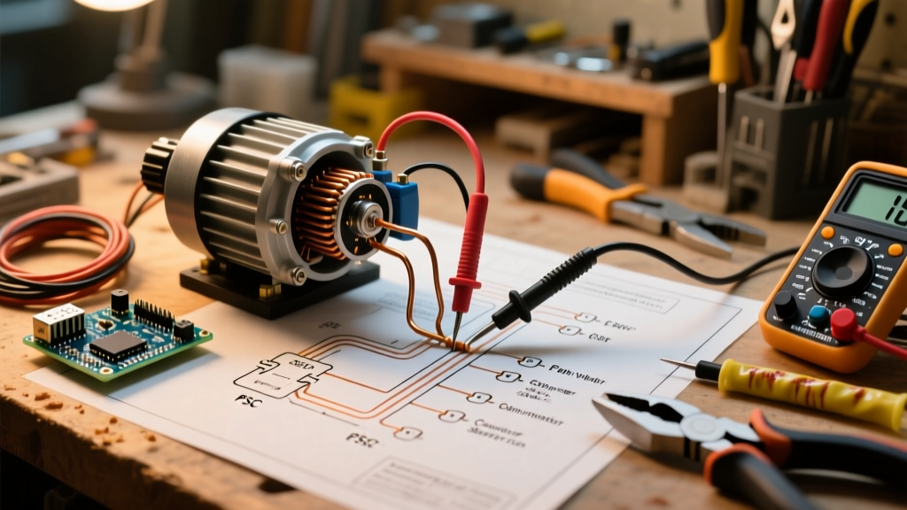
The condenser fan and indoor blower motors in most RV AC units are Permanent Split Capacitor (PSC) motors. These are single-phase, 120V AC motors that rely on a run capacitor to maintain the magnetic field. When sourcing an aftermarket replacement like the Fasco A068 or Dayton 4ME59 (typically priced between $85 and $145), you will encounter a standard 5-wire or 7-wire harness.
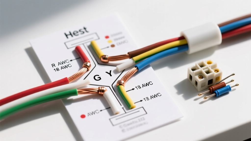
Standard Aftermarket PSC Wire Color Codes
- Brown & Brown/White Stripe: These connect exclusively to the run capacitor (usually the 5µF side of a dual 45/5µF capacitor). Never connect these to line voltage.
- White (Common/Neutral): Connects to the 'C' (Common) terminal on the contactor or the neutral bus. This completes the 120V circuit.
- Black (High Speed): Connects to the fan relay or 'F' terminal on the contactor for maximum CFM output.
- Blue (Medium Speed): Used for multi-stage cooling or heat pump defrost cycles.
- Red (Low Speed): Often used for continuous fan circulation modes.
Pro-Tip: If your OEM Coleman Mach motor uses a proprietary 3-wire harness with a built-in capacitor module, you must bypass the OEM module and wire a standard external 370V/440V run capacitor to the new aftermarket motor's brown wires to ensure proper torque and prevent thermal overload trips.
Mapping the CSR Compressor Terminals (C, S, R)
The compressor is the heart of the RV AC unit, utilizing a Capacitor Start/Run (CSR) or standard PSC hermetic compressor. The terminal block on the side of the compressor features three pins: C (Common), S (Start), and R (Run). If the labels are obscured by corrosion or missing entirely, you can identify them using a digital multimeter set to Ohms (Ω).
The Ohmmeter Identification Rule
- Measure the resistance between all three pairs of terminals (1-2, 2-3, 1-3).
- Highest Resistance (e.g., 4.5Ω): This is the Start (S) to Run (R) reading.
- Medium Resistance (e.g., 3.0Ω): This is the Start (S) to Common (C) reading.
- Lowest Resistance (e.g., 1.5Ω): This is the Run (R) to Common (C) reading.
The terminal that is part of the two highest resistance readings is your Start (S) pin. The terminal shared between the lowest and medium readings is your Common (C) pin. Connect the 'S' pin to the 'HERM' terminal on your dual run capacitor, 'C' to the contactor line, and 'R' to the 'C' (Compressor) terminal on the capacitor.
Step-by-Step Wiring & Capacitor Discharge Protocol
Safety is paramount. RV AC capacitors store lethal amounts of DC voltage even when disconnected from shore power. The OSHA electrical safety guidelines strictly mandate lockout/tagout and energy dissipation before handling electrical components.
- Isolate Power: Turn off the specific AC breaker in the RV's main distribution panel AND unplug the shore power cord. Do not rely solely on the thermostat.
- Discharge the Capacitor: Never short the terminals with a screwdriver; this damages the internal dielectric and can cause an explosion. Use a dedicated capacitor discharge tool or a 20,000-ohm, 5-watt bleeder resistor with insulated alligator clips. Bridge the 'C' and 'FAN' terminals, then the 'C' and 'HERM' terminals for 5 seconds each.
- Verify Zero Energy:Use your multimeter in DC Volts mode to confirm the capacitor reads 0.0V.
- Map and Label: Before disconnecting the old motor, use painter's tape to label every wire according to its terminal destination (e.g., 'Contactor T1', 'Cap HERM').
- Terminate: Use 1/4-inch insulated female spade connectors. Crimp with a ratcheting crimper to ensure a gas-tight connection, preventing vibration-induced arcing on the road.
Troubleshooting Matrix: Multimeter Readings & Failure Modes
| Symptom | Probable Cause | Multimeter Test & Solution |
|---|---|---|
| Humming, fan won't spin | Failed run capacitor or seized bearing | Test capacitor with a capacitance meter. If reading is >10% below rated µF (e.g., reads 4.1µF on a 5µF cap), replace it. |
| Compressor trips 30A main breaker instantly | Shorted compressor windings to ground | Test Ohms from each terminal (C, S, R) to the copper ground line. Any reading below 500kΩ indicates a grounded compressor. Replace unit. |
| Motor runs hot and shuts off after 3 mins | Thermal overload tripping due to low voltage | Check shore pedestal voltage. If below 108V under load, install a hard-start kit or use an auto-transformer boost. |
| Blower runs backward | Incorrect capacitor wiring | Verify the brown and brown/white wires are on the correct capacitor terminals and not swapped with line voltage. |
Overcoming Generator Voltage Drop with Hard-Start Kits
A common issue in the RV community is the AC compressor failing to start when running off a portable inverter generator (like the Honda EU3000iS or Predator 3500). Inverter generators produce power with higher Total Harmonic Distortion (THD) and experience severe voltage sag during the compressor's Locked Rotor Amp (LRA) surge, which can exceed 60 amps for a fraction of a second.
To resolve this, integrate a hard-start kit, such as the Supco SPP6 (approx. $25). This device combines a PTC (Positive Temperature Coefficient) relay with a heavy-duty start capacitor (usually 43-52µF). Wire the SPP6 directly across the existing run capacitor's 'C' and 'HERM' terminals. The start capacitor provides a massive phase-shifted torque boost to spin the compressor past the critical LRA threshold in milliseconds, reducing the amperage spike by up to 50%. This modification is considered a best practice by the RV Industry Association (RVIA) for off-grid and boondocking applications.
OEM vs. Aftermarket Motor Replacements: Cost & Fitment
When your AC electric motor wiring diagram reveals a burnt-out fan motor, you face a sourcing decision. OEM replacement motors from Dometic or Carrier often cost between $220 and $310 and may require a 2-week backorder. Conversely, universal aftermarket motors from Fasco, Dayton, or A.O. Smith Century cost between $85 and $160 and are available at most local HVAC supply houses.
When using an aftermarket motor, pay strict attention to the shaft diameter (usually 1/2-inch or 3/8-inch) and the rotation direction. Many universal motors feature reversible rotation via a simple plug swap on the stator harness, but you must verify the CFM rating matches the OEM spec (typically 800-1000 CFM for 13,500 BTU RV units) to prevent the evaporator coil from icing up due to insufficient airflow.