
The Critical Intersection of Wire Gauge and Electric Motor Wiring
When it comes to electric motor wiring, simply matching the nameplate amperage to a standard wire gauge chart is a recipe for premature equipment failure, voltage drop, and failed electrical inspections. In 2026, with the widespread adoption of IE4 and IE5 premium-efficiency motors and complex Variable Frequency Drives (VFDs), the thermal and electromagnetic demands on motor conductors have evolved significantly.
This comprehensive reference guide cuts through the noise, providing actionable, NEC-compliant data on wire gauge sizing, phase color codes, and the hidden edge cases—like VFD harmonic distortion and the NEC 240.4(D) exception—that separate master electricians from amateurs.
Decoding Electric Motor Wiring Color Codes
Unlike standard branch circuit wiring, electric motor wiring color codes depend heavily on whether you are wiring the supply side (from the breaker to the starter) or the load side (from the starter to the motor terminals). Furthermore, global harmonization has created distinct differences between North American (NEC/NEMA) and International (IEC) standards.
Supply Side: 3-Phase AC Color Standards
According to the National Electrical Code (NEC), specific voltage systems mandate specific phase colors to prevent catastrophic cross-voltage connections. The NFPA 70 (NEC) outlines the following standard identifiers for 3-phase systems:
| System Voltage | Phase A | Phase B | Phase C | Neutral / Ground |
|---|---|---|---|---|
| 208Y/120V | Black | Red | Blue | White / Green |
| 480Y/277V | Brown | Orange | Yellow | Gray / Green |
| 240V Delta (High-Leg) | Black | Orange (High-Leg) | Red | White / Green |
2026 Field Note: The 'High-Leg' (or 'Wild Leg') on a 240V Delta system carries 208V to neutral. The NEC strictly mandates this leg be identified by the color Orange. Miswiring a 120V control circuit to the high-leg will instantly destroy motor control boards.
Load Side: NEMA Motor Lead Markings
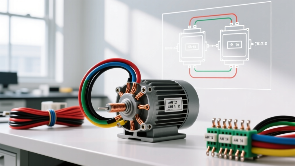
When opening a motor peckerhead (connection box), you will rarely find colored wires. Instead, the NEMA MG-1 standard requires motor leads to be identified by alphanumeric tags (e.g., T1, T2, T3). For a standard 9-lead dual-voltage 3-phase motor, the leads are numbered T1 through T9. The color of the wire insulation inside the motor casing is typically natural or black, making the printed heat-shrink markers the only reliable identification method. Always use a multimeter to verify continuity between T-pairs before energizing.
Wire Gauge Selection: The NEC Article 430 Framework
Sizing conductors for electric motor wiring is governed by NEC Article 430, not the standard Article 210 rules used for lighting and receptacles. Motors draw massive inrush currents (Locked Rotor Amps, or LRA) that can be 6 to 8 times their Full Load Amps (FLA). Therefore, wire gauge must be calculated using a specific continuous-load multiplier.
The 125% Rule and the 240.4(D) Misconception
NEC 430.22 requires motor branch circuit conductors to have an ampacity of no less than 125% of the motor's FLA as listed on the nameplate (or NEC Table 430.250 if the nameplate is missing).
The Expert Edge Case: Many junior electricians mistakenly apply NEC 240.4(D) (the 'small conductor rule', which limits 14 AWG to 15A, 12 AWG to 20A, and 10 AWG to 30A breakers) to motor circuits. However, NEC 430.52 overrides 240.4(D). Because motor overload relays protect the wire from running overloads, the branch circuit breaker only protects against short circuits. Therefore, you are legally permitted to use a 40A breaker on 10 AWG wire for a motor circuit, provided the motor starter's internal overloads are sized correctly. Understanding this prevents unnecessary upsizing of copper and saves hundreds of dollars per installation.
NEC Table 430.250 & Recommended AWG Chart (Copper, 75°C)
Below is a quick-reference matrix for 3-phase AC motors. Wire gauges are selected based on the 125% FLA calculation, referencing the 75°C column of NEC Table 310.16.
| Motor HP | 230V FLA | 230V Min. AWG | 460V FLA | 460V Min. AWG |
|---|---|---|---|---|
| 1 HP | 4.2A | 14 AWG | 2.1A | 14 AWG |
| 3 HP | 9.6A | 14 AWG | 4.8A | 14 AWG |
| 5 HP | 15.2A | 12 AWG | 7.6A | 14 AWG |
| 10 HP | 28.0A | 10 AWG | 14.0A | 12 AWG |
| 15 HP | 42.0A | 8 AWG | 21.0A | 10 AWG |
| 25 HP | 68.0A | 4 AWG | 34.0A | 8 AWG |
| 50 HP | 130.0A | 1/0 AWG | 65.0A | 4 AWG |
Note: Always verify the motor nameplate FLA. The NEC table values are only to be used if the nameplate is illegible or missing, per NEC 430.6(A)(1).
The Hidden Killer: VFD Cabling and Insulation Breakdown
In 2026, over 60% of new industrial electric motor wiring installations involve Variable Frequency Drives (VFDs). Standard THHN wire utilizes PVC insulation, which is highly susceptible to the high-frequency PWM (Pulse Width Modulation) waves generated by VFDs. The rapid voltage spikes (dV/dt) cause 'partial discharge'—microscopic electrical treeing inside the PVC insulation. This leads to ground faults and motor burnouts within 6 to 14 months.
Solution: XHHW-2 and Shielded VFD Cables
For any electric motor wiring connected to a VFD, you must abandon THHN and use XHHW-2 (Cross-Linked Polyethylene / XLPE insulation) or a dedicated shielded VFD cable (such as Lapp ÖLFLEX VFD 2XL). XLPE has a much higher dielectric strength and resists partial discharge. Furthermore, the symmetric grounding conductors and copper braid shielding in dedicated VFD cables prevent electromagnetic interference (EMI) from corrupting nearby PLC and sensor networks.
- 12 AWG THHN Cost: ~$0.65 per foot (Fails prematurely on VFDs)
- 12 AWG XHHW-2 Cost: ~$1.05 per foot (Industry standard for VFDs)
- 12 AWG Shielded VFD Cable: ~$2.80 per foot (Required for sensitive medical/cleanroom environments)
Step-by-Step Sizing Example: 10 HP, 460V 3-Phase Motor
Let us walk through a real-world scenario to solidify these concepts. You are wiring a 10 HP, 460V, 3-phase conveyor motor located 180 feet from the MCC (Motor Control Center).
- Find FLA: Nameplate reads 13.2A.
- Calculate Conductor Ampacity: 13.2A × 1.25 = 16.5A.
- Select Wire Gauge: 12 AWG copper (rated 25A at 75°C) is sufficient for the base ampacity.
- Check Voltage Drop: Using the formula VD = (√3 × K × I × L) / CM (where K=12.9 for copper, L=180ft, CM=6530 for 12 AWG).
VD = (1.732 × 12.9 × 13.2 × 180) / 6530 = 8.1 Volts.
Percentage Drop = (8.1 / 460) × 100 = 1.76%. - Final Verdict: Because the voltage drop is well under the NEC recommended 3% limit for branch circuits, 12 AWG XHHW-2 is the perfect, code-compliant choice. If the run was over 300 feet, you would need to upsize to 10 AWG strictly to mitigate voltage drop, even though the ampacity requires only 12 AWG.
Frequently Asked Questions (FAQ)
Can I use aluminum wire for electric motor wiring?
Yes, but with strict caveats. Aluminum is highly cost-effective for large feeders (e.g., 250 kcmil for a 200 HP motor). However, aluminum creeps under pressure and oxidizes rapidly. You must use AA-8000 series alloy aluminum, apply antioxidant compound (like Noalox), and torque lugs to the manufacturer's exact inch-pound specifications. Never use aluminum for the flexible whip connecting the junction box to the motor housing due to vibration fatigue.
Why does my single-phase motor have 6 leads instead of 3?
Single-phase motors often feature start and run windings, alongside a centrifugal switch or start capacitor relay. The 6 leads (typically labeled T1-T5, T8, etc.) allow you to reverse the motor's rotation by swapping the start winding leads relative to the run winding leads. Consult the specific manufacturer's wiring diagram on the motor's nameplate, as color codes for single-phase internal leads vary wildly between brands like Baldor, Leeson, and WEG.
How does ambient temperature affect my wire gauge choice?
NEC Table 310.15(B)(1) mandates temperature correction factors. If your motor is located in a boiler room where the ambient temperature reaches 113°F (45°C), you must multiply the wire's base ampacity by 0.82. A 12 AWG wire rated for 25A drops to an effective 20.5A. In high-heat environments, always upsize your conductors by at least one gauge to compensate for thermal derating and prevent nuisance tripping of the motor overloads.
Final Thoughts on Motor Circuit Integrity
Proper electric motor wiring extends far beyond stripping a wire and tightening a lug. By respecting the 125% continuous load rule, leveraging the Article 430 exceptions for OCPD sizing, and upgrading to XLPE insulation for VFD applications, you ensure decades of reliable motor operation. For deeper diagnostics on motor current and power quality, refer to testing guidelines from authorities like Fluke's electrical testing division to verify your installations post-commissioning.