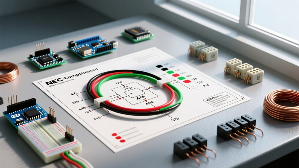

The Anatomy of a Generator Wiring Diagram and Electrical Schematics
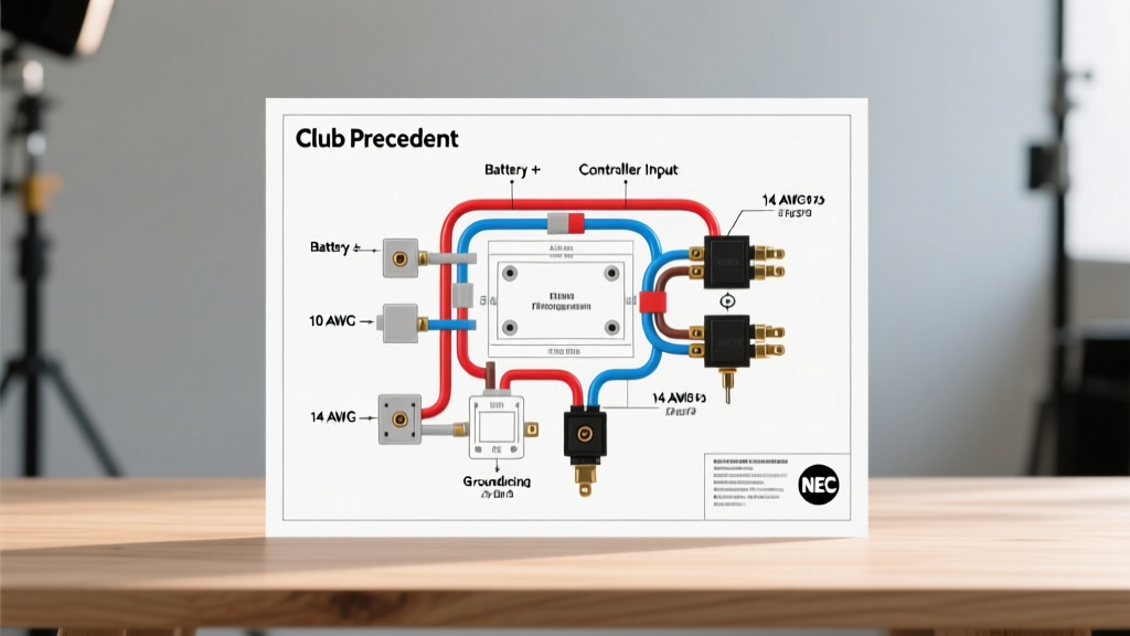
When installing or troubleshooting a standby or portable power system, understanding the difference between a physical layout and a logical circuit map is critical. A generator wiring diagram and electrical schematics serve two distinct but complementary purposes. The wiring diagram illustrates the physical routing of cables, terminal block locations, and physical wire color codes. In contrast, the electrical schematic provides the logical flow of current, detailing how the alternator, voltage regulator, automatic transfer switch (ATS), and control board interact.
As of 2026, modern standby systems like the Generac Guardian Series and Kohler 20RESCL integrate complex digital communication protocols alongside traditional 240V split-phase power circuits. Misinterpreting a schematic label (like N1 vs. T1) or selecting the wrong American Wire Gauge (AWG) can result in catastrophic ATS failure, voltage drop, or severe fire hazards. This guide bridges the gap between schematic logic and physical wire gauge selection, strictly adhering to the latest National Electrical Code (NEC) standards.
NEC Wire Color Codes for Generator Transfer Switches
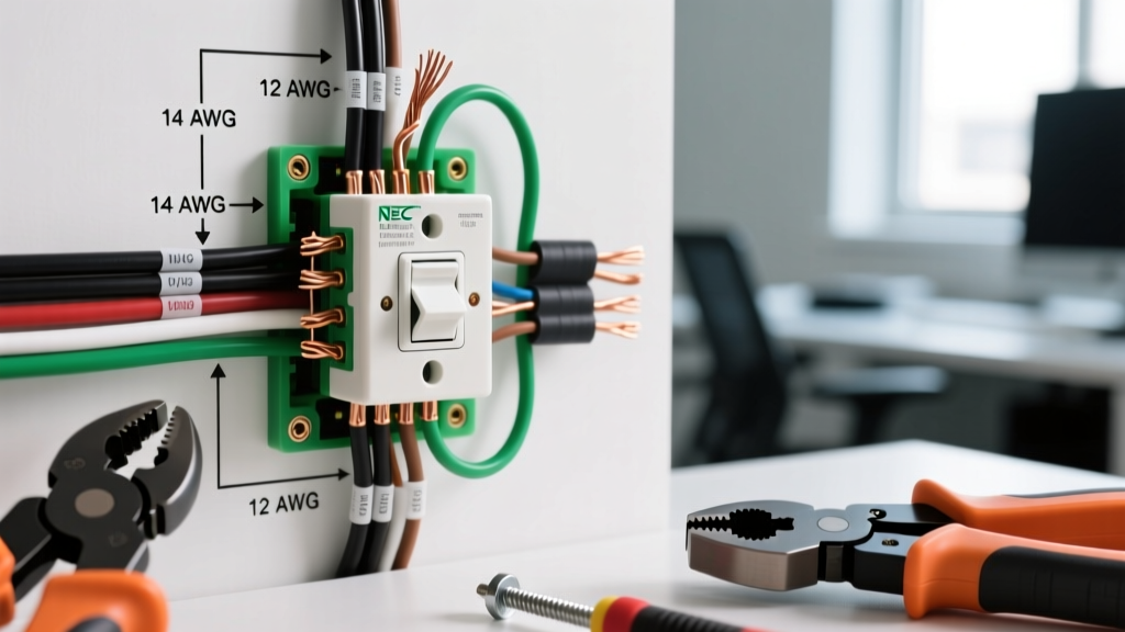
The NEC (NFPA 70) mandates specific color coding for power and grounding conductors to ensure safety and uniformity across installations. When reading your generator wiring diagram, you will map schematic terminal labels to these physical wire colors. Below is the definitive reference for a standard 240V single-phase residential standby generator connected to a service-rated ATS.
| Schematic Label | Function | NEC Insulation Color (Copper) | Typical AWG (100A - 200A) | NEC Article Reference |
|---|---|---|---|---|
T1 / L1 |
Hot Leg 1 (Power) | Black | 3 AWG to 2/0 AWG | Art. 310.12 |
T2 / L2 |
Hot Leg 2 (Power) | Red | 3 AWG to 2/0 AWG | Art. 310.12 |
N / W |
Neutral (Grounded) | White or Gray | 3 AWG to 2/0 AWG | Art. 200.6 |
GND / EG |
Equipment Ground | Bare, Green, or Green/Yellow | 6 AWG to 4 AWG | Art. 250.122 |
N1 |
Control Wire 1 (120V) | Blue or Yellow | 14 AWG | Art. 725 / 300.2 |
N2 |
Control Wire 2 (120V) | Yellow or Blue | 14 AWG | Art. 725 / 300.2 |
Sizing the Equipment Grounding Conductor (EGC)
A common edge case in generator wiring diagrams is undersizing the ground wire. According to NEC Table 250.122, the EGC must be sized based on the rating of the overcurrent protective device (OCPD) protecting the circuit, not the ampacity of the current-carrying conductors. For a 200-amp ATS protected by a 200A breaker, you must use a minimum 6 AWG copper or 4 AWG aluminum ground wire, regardless of the fact that the hot wires are 2/0 AWG.
Control Circuits vs. Power Circuits: Decoding N1 and N2
In any generator electrical schematic, the power circuits (T1, T2, N) handle the heavy load, but the control circuits (N1, N2) are the brain of the operation. The N1 and N2 wires carry 120V AC from the generator's alternator directly to the ATS control board. They serve two vital functions:
- Utility Sensing: The ATS uses
N1andN2to monitor the generator's voltage output. If the voltage drops below a preset threshold (usually 85% of nominal), the ATS will shed the load or trigger an alarm. - Battery Charging & Logic Power: These wires power the ATS logic board and the internal battery charger that keeps the generator's 12V DC starting battery topped off.
2026 Pro-Tip for Smart ATS Panels: Modern systems like the Generac PWRview or Kohler OnCue Plus utilize RS-485 or CAN bus communication lines alongside
N1/N2. These data wires are typically 18 AWG twisted pair (often colored purple/white). Never run these low-voltage data cables in the same conduit as the 240VT1/T2power lines, as electromagnetic interference (EMI) will corrupt the telemetry data and cause phantom fault codes.
Calculating Wire Gauge for Long-Distance ATS Runs
Electrical schematics rarely account for physical distance. If your generator is located 100 feet away from the ATS, standard ampacity tables are insufficient due to voltage drop. The NEC recommends a maximum 3% voltage drop on branch circuits and feeders.
The Voltage Drop Formula for Single-Phase Generators
To calculate the exact wire gauge needed for your specific run, use the following formula:
Voltage Drop = (2 x K x I x L) / CM
- K: Direct Current constant (12.9 for Copper, 21.2 for Aluminum)
- I: Current in Amps (e.g., 150A)
- L: One-way length of the wire in feet (e.g., 120 ft)
- CM: Circular Mils of the wire (found in NEC Chapter 9, Table 8)
Real-World Scenario: You are installing a 150A Generac generator 120 feet from the main ATS using THHN copper wire in PVC conduit. A standard 1 AWG copper wire (83,690 CM) yields a voltage drop of roughly 5.5V (2.3%), which is well within the 3% limit. However, if you upgrade to a 200A system on that same 120-foot run, 1 AWG will result in a 3.1% drop. You must step up to 1/0 AWG to maintain code compliance and ensure the ATS contactor coils receive sufficient voltage to pull in reliably.
Step-by-Step: Tracing Schematics from Alternator to ATS
When troubleshooting a 'No Crank' or 'Fail to Transfer' error, follow this logical path on your electrical schematic:
- Locate the Alternator Output Terminals: Find where
T1,T2, andNoriginate at the stator windings. - Trace the Main Breaker: Follow the lines to the generator's internal main circuit breaker (MCB). Ensure the physical wire gauge matches the MCB rating (e.g., 3 AWG for a 100A MCB).
- Identify the Control Tap: Locate where
N1andN2branch off fromT1andT2(or the neutral bus). Verify the 14 AWG control wires are secured under the correct terminal lugs. - Follow to the ATS: Trace
N1andN2to the ATS terminal block. Check the schematic for any inline fuses (typically 5A or 10A glass fuses on the control board). A blown 5A fuse on theN1line is a leading cause of ATS logic failure.
Common Wiring Mistakes and Edge Cases
Even experienced electricians can misinterpret complex generator wiring diagrams. Watch out for these specific failure modes:
- Swapped L1 and L2 (T1/T2): While a standard 240V resistive load won't care if L1 and L2 are swapped, modern smart panels and certain HVAC compressors rely on correct phase rotation or specific leg loading. Always match the schematic's
T1to the ATSL1and the main panel's Phase A. - Undersized Neutral in Non-Linear Loads: If the generator powers a facility with heavy non-linear loads (e.g., large LED lighting arrays, VFDs, or server racks), triplen harmonics can accumulate on the neutral. In these edge cases, the NEC may require the neutral wire to be oversized by 150% to 200% compared to the hot legs, despite the schematic showing them as equal.
- Improper Bonding (SDS vs. SDS-B): Separately Derived Systems (SDS) require a neutral-to-ground bond at the generator. Non-SDS systems (like portable generators connected via a transfer switch that does not switch the neutral) must have the bond removed. Misreading the bonding schematic can create parallel neutral paths, causing ground fault protection to trip instantly.
FAQ: Generator Schematics and Wire Sizing
Can I use aluminum wire for generator power connections?
Yes, aluminum (specifically XHHW-2 or THWN-2 AA-8000 series alloy) is highly cost-effective for long runs between the generator and the ATS. However, you must upsize by two AWG sizes compared to copper to achieve the same ampacity (e.g., use 1/0 AWG Aluminum instead of 3 AWG Copper for a 100A run). Always apply an anti-oxidant compound like Noalox to aluminum terminations to prevent thermal expansion failures at the ATS lugs.
Why does my schematic show a wire labeled '0' or 'B0'?
In many Kohler and Cummins electrical schematics, 0 or B0 designates the common DC ground for the 12V control circuit, not the AC neutral. This wire is typically 12 AWG or 14 AWG and connects to the battery negative terminal and the chassis ground bus. Confusing this with the AC neutral (N) will instantly destroy the voltage regulator.
Where can I find the official NEC guidelines for optional standby systems?
All generator wiring, transfer switch installation, and bonding requirements for residential and commercial standby systems are governed by OSHA wiring standards and NEC Article 702 (Optional Standby Systems). For systems where life safety is dependent on power (like hospitals), refer to NEC Article 700 (Emergency Systems) and Article 701 (Legally Required Standby Systems), which enforce much stricter schematic redundancy and wire routing rules.