
The Critical Role of O2 Sensors in Modern Motor Wiring
Whether you are retrofitting a classic V8 with a modern standalone EFI system, tuning a high-performance motorcycle, or troubleshooting a small industrial engine, understanding the wiring diagram for O2 sensor integration is non-negotiable. The oxygen sensor acts as the chemical sniffer for your Engine Control Unit (ECU), dictating fuel trims in real-time. A poorly wired sensor will result in erratic air-fuel ratios (AFR), catalytic converter damage, and severe engine knock.
As of 2026, the aftermarket and OEM landscape has largely bifurcated into two camps: traditional narrowband zirconia sensors for basic emissions compliance, and advanced wideband sensors for precise closed-loop tuning. This tutorial breaks down the exact wiring architectures, pinouts, and diagnostic procedures for both.
Decoding the Wiring Diagram for O2 Sensor Types
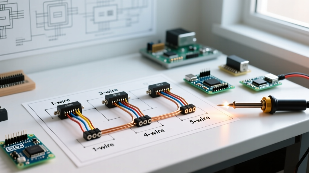
Before cutting wires or crimping terminals, you must identify your sensor type. The number of wires dictates the internal architecture and how the ECU must be configured.
1-Wire and 2-Wire Narrowband Sensors
Found primarily on older motors and basic small engines, these sensors lack an internal heater. They rely entirely on exhaust gas temperature (typically requiring 600°F+) to become active.
- 1-Wire: The single wire is the signal output (usually 0.1V to 0.9V). The sensor grounds directly through its threaded metal body to the exhaust manifold or engine block.
- 2-Wire: Adds a dedicated ground wire. This is used when the exhaust system is powder-coated, ceramic-coated, or rusted, preventing a reliable chassis ground.
3-Wire and 4-Wire Heated Narrowband Sensors
To meet stricter emissions standards, manufacturers added an internal heating element to bring the zirconia element up to operating temperature (approx. 650°F) within seconds of a cold start.
- 3-Wire: Signal wire, Heater Power (+12V), and Heater Ground. The signal still grounds through the sensor body.
- 4-Wire: The modern standard for narrowband. Includes Signal, Signal Ground, Heater Power, and Heater Ground. This isolated signal ground prevents alternator whine and chassis noise from corrupting the millivolt signal sent to the ECU.
5-Wire Wideband Sensors (e.g., Bosch LSU 4.9)
Wideband sensors do not just switch at stoichiometry (14.7:1); they measure exact AFR from 10:1 to 20:1. The industry-standard Bosch LSU 4.9 uses a complex 5-wire (or 6-pin connector) setup featuring a pump cell, a reference cell, and a calibration resistor.
Step-by-Step Motor Wiring Tutorial: 4-Wire Narrowband
Let us walk through a practical installation of a standard 4-wire Denso or NGK narrowband sensor into an aftermarket EFI harness. For this example, we will use the popular NGK/NTK L1H1 equivalent narrowband architecture.
⚠️ SAFETY & RELIABILITY CALLOUT: Never solder O2 sensor wires directly. High exhaust heat and engine vibration will cause solder joints to fatigue and snap. Always use adhesive-lined marine-grade heat shrink crimp connectors (e.g., Ancor or Molex) or OEM-style Weather-Pack terminals.- Identify the Pinout: Consult your specific sensor's datasheet. A common Denso 4-wire color code is: Black (Signal), White (Signal Ground), and two Blue/White wires (Heater circuit, non-polarized).
- Wire the Heater Circuit: The heater draws a massive 8 to 12 amps on initial startup. You must use 14 AWG to 16 AWG wire. Connect one heater wire to a 12V ignition-switched relay. Connect the second heater wire to the ECU's 'Heater Control' pin. Modern 2026 ECUs use Pulse Width Modulation (PWM) on this ground circuit to prevent thermal shock to the ceramic element.
- Wire the Signal Circuit: Use 18 AWG or 20 AWG shielded twisted-pair wire. Connect the signal wire directly to the ECU's O2 input pin. Connect the signal ground to the ECU's dedicated sensor ground pin—never to the engine block or chassis.
- Shielding: Ground the shield drain wire of the twisted pair at the ECU end only. Grounding both ends creates a ground loop, introducing alternator noise into the fuel map.
Diagnostic Matrix: Multimeter Testing & Failure Modes
When a motor runs rich or throws a P0130/P0135 code, use a digital multimeter (DMM) to isolate the fault. Below is a diagnostic matrix for 4-wire narrowband and 5-wire wideband systems.
| Test Parameter | Expected Reading (Engine Off) | Expected Reading (Engine Running/Closed Loop) | Common Failure Mode if Out of Spec |
|---|---|---|---|
| Heater Resistance (Narrowband) | 2.0 to 14.0 Ohms | N/A | Internal heater trace broken (Code P0135). Replace sensor. |
| Heater Resistance (Bosch LSU 4.9) | 2.5 to 3.5 Ohms (Pins 3 & 4) | N/A | Heater circuit short. Will blow ECU internal driver. |
| Signal Voltage (Narrowband) | 0.45V (Bias voltage from ECU) | Oscillating 0.1V to 0.9V (1-2 Hz) | Stuck at 0.1V (Lean/Exhaust leak) or 0.9V (Rich/Fouled). |
| Signal Ground Offset | 0.00V | Less than 0.05V (50mV) | Bad chassis ground. Offset voltage skews ECU fuel trims. |
| Wideband Pump Cell (LSU 4.9) | 75 to 150 Ohms (Pins 1 & 5) | Varies with AFR | Sensor contamination from silicone, lead, or oil ash. |
Wire Routing and EMI Mitigation in Motor Bays
The motor bay is an electrically hostile environment. The O2 sensor signal operates in the millivolt range, making it highly susceptible to Electromagnetic Interference (EMI). In 2026, with the prevalence of high-output COP (Coil-on-Plug) ignition systems and high-frequency switching alternators, EMI management is critical.
The 3-Inch Rule for High Voltage
Never route O2 sensor signal wires parallel to ignition coil power feeds, spark plug wires, or injector harnesses. If you must cross these high-voltage lines, do so at a strict 90-degree angle. Maintain a minimum 3-inch lateral separation from any EMI source.
Thermal Management
While the sensor itself is designed to live in 1,200°F exhaust gas, the wiring harness and connector are not. The PTFE (Teflon) insulation on high-end sensor pigtails can withstand roughly 400°F. If your exhaust manifold or turbocharger downpipe radiates heat exceeding this threshold, you must wrap the sensor harness in fiberglass or basalt heat-sleeving (e.g., DEI Titanium Exhaust Wrap). Keep the plastic connector body at least 8 inches away from the exhaust flange to prevent the internal locking tabs from melting and causing an intermittent connection.
Expert Tuner Tip: If your wideband controller reads erratically only when the engine is under heavy load or high RPM, you are likely experiencing EMI from the ignition system. Before replacing the $80 sensor, check your spark plug gap and ensure your ignition coils have a dedicated, clean ground strap directly to the cylinder head.
Wideband Calibration Resistor: The Hidden Component
When wiring a 5-wire or 6-pin wideband sensor like the Bosch LSU 4.9 to a standalone ECU (such as Haltech, Link, or MegaSquirt), the wiring diagram includes a critical component often overlooked by novices: the calibration resistor. This resistor is laser-trimmed at the factory and housed inside the sensor's connector. It compensates for microscopic manufacturing variances in the sensor's diffusion barrier.
If you cut the factory connector off to lengthen the harness and fail to transfer this calibration resistor into your new plug, your ECU will read AFR incorrectly by up to 1.5 points. Always preserve the OEM connector or purchase a replacement connector kit (like the Motorsport Electronics 6-pin LSU 4.9 pigtail, typically $25-$35) that includes the matched calibration resistor.
Summary of Best Practices
Mastering the wiring diagram for O2 sensor applications requires respecting both the chemical sensitivity of the sensor and the electrical fragility of the signal. Use twisted-pair shielded cables for signals, heavy-gauge wiring for heaters, and adhere strictly to isolated grounding protocols. By following these 2026-standard motor wiring practices, you ensure your ECU receives pristine data, resulting in optimal power, fuel economy, and engine longevity.