
Decoding Electrical Wiring Diagram Symbols for Conductors
When navigating complex schematics, most DIYers and junior electricians quickly learn the standard electrical wiring diagram symbols for components like resistors, capacitors, and relays. However, the symbols and alphanumeric notations used to represent wire gauges, conductor colors, and cable jackets are frequently misunderstood. Unlike components, wires are often represented by simple lines, with critical gauge and color data relegated to small text annotations or specific cross-sectional symbols. Misinterpreting these notations can lead to catastrophic undersizing, resulting in thermal runaway, melted insulation, and electrical fires.
This comprehensive reference guide bridges the gap between abstract schematic lines and physical wire selection. We will decode the specific electrical wiring diagram symbols used for wire gauges (AWG and metric), color code abbreviations, and multi-conductor cables, ensuring your 2026 projects meet both safety standards and optimal performance metrics.
Graphical vs. Alphanumeric Wire Symbols
In standard schematics, a simple solid line typically represents a generic electrical connection. However, professional electrical wiring diagrams use specific modifications to this line to denote physical cable properties:
- Single Conductor: A standard solid line, often intersected by diagonal hash marks (e.g., ///) with a number indicating the count of wires in a bundle.
- Multi-Conductor Cable: A solid line enclosed in a dashed or dotted boundary, indicating a shared outer jacket (like NM-B or MC cable).
- Shielded Cable: A solid line surrounded by a concentric circle or a braided pattern symbol, denoting an EMI/RFI shield (common in VFD motor wiring and audio systems).
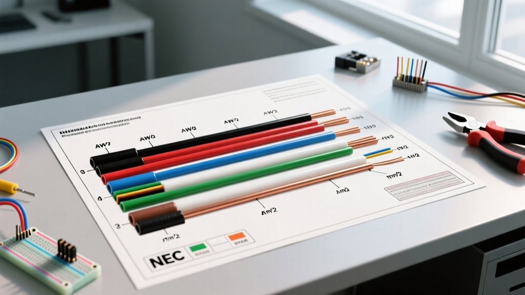
- Alphanumeric Annotations: The most critical 'symbols' for wire gauge are actually text tags placed directly above or below the wire line (e.g.,
12 AWG BKor2.5mm² BU).
Wire Gauge Notations: AWG vs. Metric (mm²)
Depending on the origin of the schematic, you will encounter either the American Wire Gauge (AWG) system or the International Electrotechnical Commission (IEC) metric system. Understanding how to translate these diagram symbols into physical wire is critical, especially when working with imported machinery or international HVAC control boards.
The Danger of Metric-to-AWG Substitution
A common edge case occurs when a US-based technician services a European-manufactured CNC machine. The schematic calls for 4.0 mm² wire. If the technician incorrectly assumes 4.0 mm² equates to 12 AWG (which is actually 3.31 mm²), the circuit will be undersized by nearly 17%. This leads to excessive voltage drop and dangerous heat accumulation at the termination lugs. Always use a precise cross-reference chart.
| Diagram Symbol (AWG) | Diagram Symbol (Metric) | Actual Diameter (mm) | Cross-Section (mm²) | Max Ampacity (60°C) | Max Ampacity (75°C) |
|---|---|---|---|---|---|
| 14 AWG / #14 | 2.0 mm² | 1.63 | 2.08 | 15A | 20A |
| 12 AWG / #12 | 3.0 mm² | 2.05 | 3.31 | 20A | 25A |
| 10 AWG / #10 | 5.0 mm² | 2.59 | 5.26 | 30A | 35A |
| 8 AWG / #8 | 10.0 mm² | 3.26 | 8.37 | 40A | 50A |
| 6 AWG / #6 | 16.0 mm² | 4.11 | 13.30 | 55A | 65A |
Note: Ampacities are based on copper conductors with standard insulation types like THHN/THWN-2 and XHHW-2, referencing standard derating tables. Always consult the NFPA NEC Guidelines for specific installation conditions.
Standard Color Code Abbreviations in Diagrams
Wiring diagrams rarely spell out full color names. Instead, they use standardized two-letter or three-letter alphanumeric symbols next to the wire gauge notation. These abbreviations differ significantly between North American (NEC) and International (IEC) standards. Mixing these up can result in connecting a 240V hot leg directly to a chassis ground.
| Abbreviation Symbol | Color | NEC Function (US/Canada) | IEC Function (Europe/Global) |
|---|---|---|---|
| BK / BLK | Black | Hot / Line 1 (120V/240V) | Line 1 (Brown is preferred) |
| RD / RED | Red | Hot / Line 2 (240V/3-Way) | Line 2 or Switched Hot |
| BU / BLU | Blue | Hot / Line 3 (277V/480V) | Neutral or Line 3 |
| WH / WHT | White | Neutral (Grounded Conductor) | Not standard for mains power |
| GN / GRN | Green | Equipment Ground | Equipment Ground (w/ Yellow stripe) |
| YE / YEL | Yellow | Hot / Line 3 (277V/480V) | Control wiring or Line 3 |
Expert Tip: Reading 'Stripe' and 'Tracer' Symbols
When a diagram shows a symbol like BK/WH or RD-BK, it denotes a wire with a base color and a tracer stripe. For example, a 'White wire with a Black tracer' is often used in 3-way switch loops to indicate that the neutral-colored wire is actually being used as a 'hot' traveler. Per modern NEC requirements, this wire must be re-identified with black tape or marker at both termination points to prevent fatal shock hazards during future maintenance.
Multi-Conductor Cable & Jacket Symbols
For residential and commercial branch circuits, diagrams use a specific 'slash' notation to represent non-metallic (NM) or metal-clad (MC) cables. Understanding this shorthand is vital for accurate material estimation.
Deconstructing the Slash Notation
A common symbol on a residential blueprint is 12/2 NM-B w/ GND. Here is how to break down this electrical wiring diagram symbol:
- 12: The AWG gauge of the individual current-carrying conductors.
- 2: The number of insulated current-carrying conductors (one Black, one White).
- NM-B: The jacket type (Non-Metallic, Type B, rated for 90°C but ampacity limited to 60°C per code).
- w/ GND: Indicates the presence of a bare copper equipment grounding conductor, which is not counted in the '2'.
If a diagram calls for 10/3 MC, you are looking at a Metal-Clad cable containing three 10 AWG insulated conductors (Black, Red, White) plus a ground, wrapped in an interlocking aluminum armor. This is frequently required in 2026 for commercial exposed-run applications where physical damage is a risk.
Sourcing and Cost Considerations for 2026
Accurately reading wire gauge symbols directly impacts your project budget. As of early 2026, copper prices have stabilized but remain historically high, hovering between $4.20 and $4.60 per pound. Consequently, the price differential between wire gauges is substantial.
- 14 AWG THHN: Approximately $0.18 to $0.22 per foot.
- 12 AWG THHN: Approximately $0.28 to $0.34 per foot.
- 10 AWG THHN: Approximately $0.45 to $0.55 per foot.
If a schematic uses a generic line symbol and fails to specify a gauge, the default assumption for a 20A receptacle circuit must be 12 AWG. Upgrading from 14 AWG to 12 AWG for a 500-foot run will cost roughly $50 to $60 more in materials alone, not including the larger wire nuts (e.g., Ideal Yellow Wing or 3M Performance Plus) and the physical effort required to strip and terminate the thicker, stiffer copper.
Troubleshooting Common Diagram Errors
Even professional schematics contain errors. When cross-referencing a wiring diagram with physical installation requirements, watch out for these specific failure modes:
- The 'Generic Line' Trap: A control schematic for an HVAC unit shows a line connecting the contactor to the compressor. The diagram omits the gauge symbol. Always verify the breaker size; if it is a 40A breaker, the wire must be 8 AWG, regardless of what the thin lines on the schematic imply.
- Temperature Rating Mismatches: A diagram specifies '90°C wire' for a high-ambient-temperature enclosure. Standard NM-B cable is not suitable here. You must source individual THHN/THWN-2 or XHHW-2 conductors rated for 90°C, and apply the correct ampacity derating factors as outlined by OSHA Wiring Design Standards.
- Stranding vs. Solid Notations: Some diagrams use a specific wavy line symbol to denote stranded wire versus a straight solid line for solid core. Stranded wire (like MTW or AWM) is mandatory for control panels subject to vibration, whereas solid wire is standard for in-wall branch circuits.
Frequently Asked Questions (FAQ)
What does a circle with a cross inside mean on a wiring diagram?
This symbol typically represents a specific connection point, a terminal block, or a wire splice. In some European schematics, it can also denote the cross-sectional area of a specific cable bundle. Always check the diagram's legend.
Can I use 14 AWG wire if the diagram symbol just shows a standard line?
Only if the circuit is protected by a 15A breaker. If the breaker is 20A, you must use 12 AWG. Never assume wire gauge based on the thickness of the line drawn in a schematic; always look for alphanumeric annotations or cross-reference the breaker/overcurrent protection device (OCPD) symbol on the same drawing.
How do I read wire gauge symbols for low-voltage or data cables?
Low voltage diagrams often use AWG but focus on categories (e.g., Cat6, 23 AWG solid) or specific multi-pair symbols (e.g., 18/2 for thermostat wire). For PoE (Power over Ethernet) applications in 2026, ensure the diagram specifies 23 AWG solid copper; avoiding 24 AWG or Copper-Clad Aluminum (CCA) is critical to prevent voltage drop and data packet loss over long runs.
Mastering these electrical wiring diagram symbols ensures that your transition from paper schematic to physical reality is safe, code-compliant, and cost-effective. For further reading on international color code harmonization, refer to the IEC International Standards database.