
The Critical Role of Safety Interlocks in Troy-Bilt Mowers
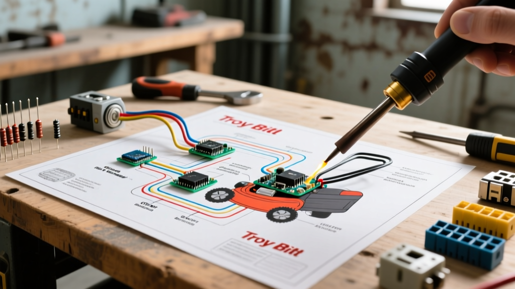
Understanding the wiring diagram for Troy Bilt riding mower models is not merely an exercise in electrical troubleshooting; it is a fundamental requirement for operator safety and legal compliance. Modern riding mowers are equipped with complex safety interlock systems designed to prevent the engine from cranking unless the brake is engaged, and to instantly kill the engine if the operator leaves the seat while the Power Take-Off (PTO) blades are spinning. Modifying, bypassing, or incorrectly repairing these circuits violates federal safety guidelines and exposes the operator to severe laceration or amputation hazards.
According to the U.S. Consumer Product Safety Commission (CPSC), tens of thousands of emergency room visits occur annually due to improper lawn mower operation and defeated safety switches. This guide provides a deep-dive, expert-level analysis of Troy-Bilt interlock schematics, diagnostic protocols, and National Electrical Code (NEC) compliance for charging infrastructure.
ANSI B71.1 Compliance and the "Dead-Man" Circuit
All Troy-Bilt riding mowers manufactured for the US market must comply with the ANSI B71.1 standard, overseen by the Outdoor Power Equipment Institute (OPEI). This standard mandates a "dead-man" control system. In electrical terms, this is achieved through a series-parallel logic gate utilizing Normally Open (NO) and Normally Closed (NC) microswitches.
- Seat Switch: Typically a NO switch that closes (completes the circuit to ground) when the operator stands up.
- PTO Switch: Closes the circuit when the blade engagement lever is pulled or the electric clutch button is pressed.
- Ignition Magneto Kill Terminal: The intersection point. If the Seat Switch AND the PTO Switch are both closed simultaneously, the circuit grounds the ignition coil's primary winding, instantly killing the spark.
Expert Warning: Bypassing the seat switch by jumping the harness connector with a copper wire is a direct violation of OSHA regulations for commercial landscaping operations and voids all manufacturer liability insurance. Always replace faulty switches with OEM Troy-Bilt/MTD parts (typically $18–$32 per switch).
Decoding the Wiring Diagram: Model-Specific Variations
Troy-Bilt, manufactured by MTD Products, utilizes different harness architectures depending on the model tier. Reading the wiring diagram for a Troy Bilt riding mower requires identifying whether your model uses a mechanical PTO engagement or an electromagnetic PTO clutch.
| Troy-Bilt Model | Engine / HP | PTO Type | Interlock Architecture | Key Wiring Spec |
|---|---|---|---|---|
| Pony (42") | Briggs & Stratton 15.5 HP | Manual Mechanical | Simple Series Loop (Seat/Brake) | 16 AWG Magneto Kill Wire |
| Bronco (42") | Kohler 19 HP | Electric Clutch | Solid-State Safety Module | 10 AWG PTO Feed (10A Fuse) |
| Mustang XP (54") | Kohler 25 HP | Electric Clutch | Multi-Node CAN/Relay Logic | 12 AWG Clutch Feed (15A Relay) |
The Solid-State Safety Module (Bronco & Mustang XP)
On higher-end models like the Bronco and Mustang XP, the wiring diagram features a centralized Safety Interlock Module (a small black resin block with a 6-pin Deutsch or Molex connector). This module monitors the brake pedal position, PTO switch, and seat switch. If the logic conditions are violated, the module internally triggers a relay that grounds the magneto. Diagnosing a faulty module requires verifying that 12VDC is present at the module's power input pin (Pin 1) and that the ground pin (Pin 6) shows less than 0.2 ohms of resistance to the chassis.
Step-by-Step Safety Interlock Diagnostic Protocol
When a Troy-Bilt mower cranks but immediately dies upon releasing the brake, or fails to crank entirely, follow this precise multimeter diagnostic sequence. You will need a digital multimeter (e.g., Fluke 117) set to Continuity/Ohms.
- Isolate the Harness: Disconnect the main wiring harness plug from the ignition switch. This prevents back-feeding voltage through the dashboard lights.
- Test the Brake Switch: Locate the brake pedal microswitch. With the pedal depressed (locked), probe the two switch terminals. You should read OL (Open Line). Release the pedal; the meter should beep, indicating continuity (<0.5 ohms). If it fails, replace the $14 OEM switch.
- Test the Seat Switch Logic: Access the connector under the seat. With no weight on the seat, probe the harness side (not the switch side) for continuity to chassis ground. On most MTD/Troy-Bilt diagrams, the seat switch provides a ground path to the safety module only when empty. If you read continuity to ground while seated, the switch is internally shorted and killing the engine.
- Verify the PTO Switch Isolation: Ensure the PTO lever is OFF. Probe the PTO switch output wire (usually yellow or green). It must read OL to ground. If it reads continuity, the switch is stuck closed, trickling the safety module into thinking the blades are engaged, which prevents the engine from cranking.
NEC Code Compliance for Mower Charging Stations
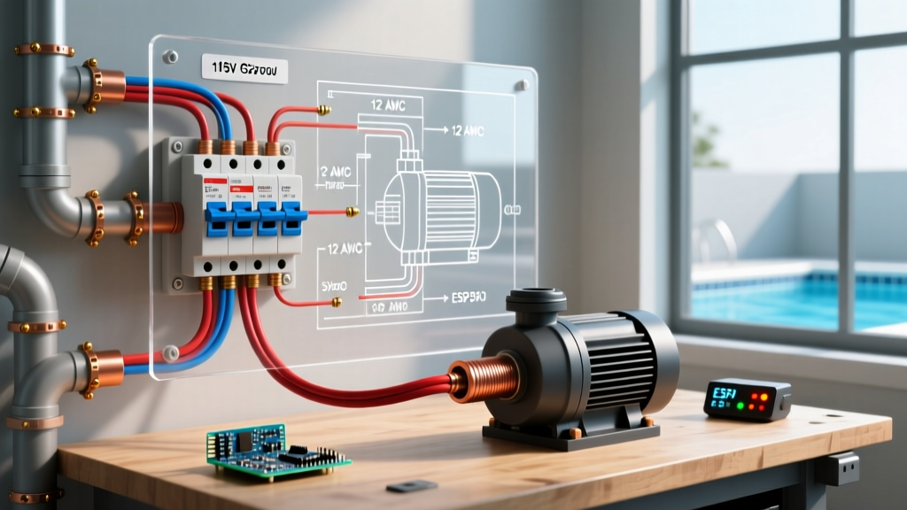
Riding mowers with 12V batteries require periodic trickle charging, especially during winterization. Installing a dedicated charging receptacle in your garage or outdoor shed requires strict adherence to the National Electrical Code (NEC) Article 210.8.
Garage and Shed GFCI Mandates
Under NEC 210.8(A)(2), all 125-volt, single-phase, 15- and 20-ampere receptacles installed in garages must have Ground-Fault Circuit-Interrupter (GFCI) protection. Furthermore, if you are running a circuit to an outdoor shed or pole barn for mower storage, NEC 210.8(F) mandates GFCI protection for all outdoor and outbuilding receptacles.
- Wiring Method: Use 12 AWG THHN copper conductors pulled through 1/2-inch Schedule 80 PVC conduit for underground runs to a shed.
- Receptacle Type: Install a weather-resistant (WR) TR (Tamper-Resistant) GFCI receptacle in a while-in-use bubble cover.
- Transformer Isolation: Ensure your battery tender is UL-listed for outdoor/damp locations if left plugged into an exterior shed receptacle.
Wire Gauge Selection and Routing Standards
When repairing a damaged harness or replacing an electric PTO clutch on a Mustang XP, using the correct SAE J1128 automotive wire gauge is critical to prevent voltage drop and thermal fires. The electric PTO clutch draws between 3.5 and 5.0 amps continuously. Undersized wiring causes voltage drop, resulting in a weak magnetic field, clutch slippage, and premature bearing failure.
| Circuit Function | Minimum AWG (Copper) | Insulation Type | Overcurrent Protection |
|---|---|---|---|
| Battery to Starter Solenoid | 6 AWG | SAE J1128 (SGX) | 150A MIDI Fuse |
| Electric PTO Clutch Feed | 10 AWG | Cross-Linked Polyethylene (XLPE) | 10A Inline AGC Fuse |
| Alternator Stator to Regulator | 14 AWG | PVC / Primary Automotive | 20A Main Harness Fuse |
| Interlock Logic / Magneto Kill | 16 AWG | PVC / Primary Automotive | Protected via Ignition Switch |
Common Failure Modes and Edge Cases
1. Corroded Spade Connectors in the PTO Circuit
Troy-Bilt Bronco models are highly susceptible to moisture ingress at the PTO clutch connector, located directly beneath the mower deck. Road salt and fertilizer accelerate galvanic corrosion on standard brass spade terminals. Fix: Cut off the corroded terminals and solder in marine-grade, heat-shrink butt connectors with dielectric grease. Do not use standard crimp connectors in this high-vibration, high-moisture zone.
2. Voltage Drop Across the Ignition Switch
If the mower's 12V accessories (headlights, electric PTO) dim when the engine is idling, the issue is rarely the alternator. It is usually a voltage drop across the aging ignition switch contacts. Measure the voltage at the battery (should be ~13.8V running). Then measure at the PTO switch input. If the PTO switch reads below 12.5V, the ignition switch is failing internally and must be replaced to prevent clutch chatter.
3. Aftermarket Seat Switch Defeats
Purchasing a used Troy-Bilt mower? Inspect the wiring diagram harness under the seat. A common edge case is the previous owner zip-tying the seat switch plunger down in the "seated" position and hiding it beneath the seat pan. This defeats the ANSI B71.1 safety requirement. Always trace the physical wire from the seat pan to the main harness to ensure the OEM switch is intact and functional.
Summary of Best Practices
Navigating the wiring diagram for a Troy Bilt riding mower requires a methodical approach grounded in electrical safety and code compliance. Never bypass interlock switches, always utilize marine-grade connectors for under-deck repairs, and ensure your charging infrastructure meets current NEC GFCI mandates. By adhering to these OEM specifications and ANSI standards, you guarantee both the longevity of your equipment and the physical safety of the operator.