
Restoring the 1963-1965 John Deere 110 Electrical System
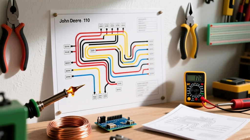
The John Deere 110, introduced in 1963, represents a cornerstone of vintage lawn and garden tractor engineering. Powered predominantly by the robust 8 HP Kohler K181S engine, these machines rely on a 12-volt, negative-ground electrical system utilizing a starter/generator rather than a modern alternator. After six decades of exposure to engine heat, vibration, and moisture, the original cloth and PVC-insulated wiring harnesses become brittle, leading to voltage drops, parasitic draws, and catastrophic short circuits. When consulting a wiring diagram for John Deere 110 models, restorers must bridge the gap between vintage schematic logic and modern automotive wire standards. This step-by-step walkthrough provides a comprehensive guide to completely rewiring your JD 110, ensuring reliable starts and stable charging characteristics for years to come.
Core 12V Negative-Ground Architecture
Before cutting a single wire, it is critical to confirm your tractor's ground polarity. While older John Deere models (like the early Model M) utilized a 6-volt positive-ground system, the JD 110 was engineered from the factory as a 12-volt negative-ground system. Reversing this polarity will instantly destroy the solid-state components in modern replacement voltage regulators and cause the ammeter to read backward. The core architecture revolves around four primary nodes: the 12V battery, the Delco or Prestolite starter/generator, the mechanical voltage regulator (VR), and the dash-mounted ignition/ammeter cluster.
Wire Gauge and Routing Matrix
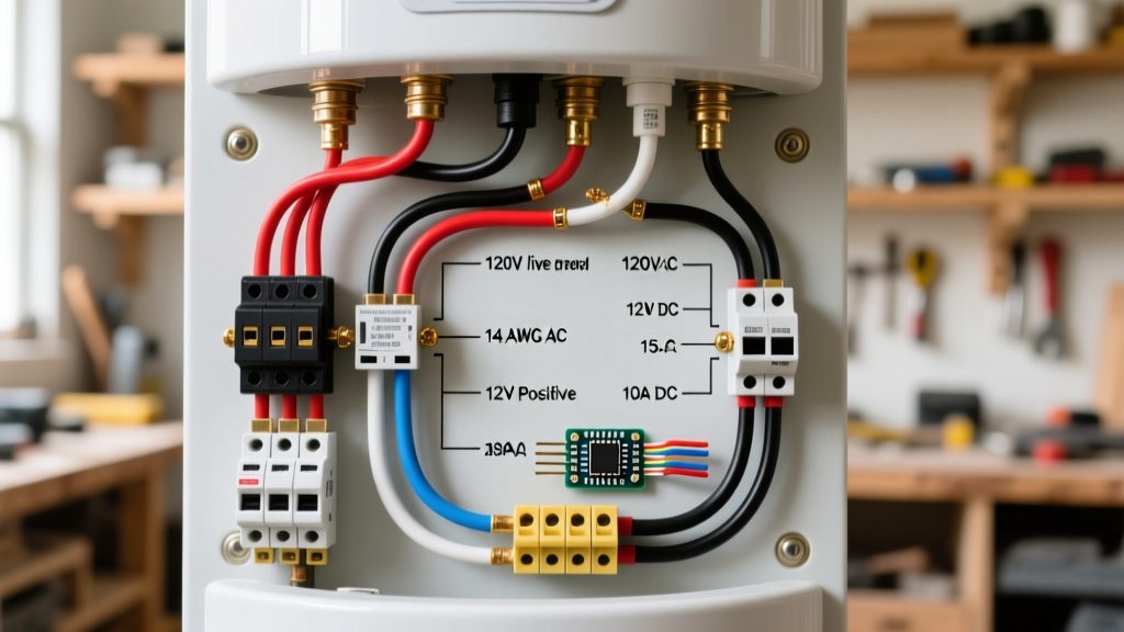
Selecting the correct wire gauge is non-negotiable. Undersized wires in the charging circuit will overheat and melt. We recommend using GXL (Cross-linked Polyethylene) wire for all engine-bay routing due to its 155°C heat resistance, which vastly outperforms standard PVC wire. For exact specifications based on NFPA 70 (National Electrical Code) ampacity guidelines for low-voltage DC systems, refer to the matrix below:
| Circuit Path | Wire Gauge (AWG) | Wire Type | Recommended Color Code |
|---|---|---|---|
| Battery (+) to Ammeter / Starter | 10 AWG | GXL Stranded | Red |
| Voltage Regulator 'BAT' to Harness | 10 AWG | GXL Stranded | Red |
| Starter/Gen 'ARM' to VR 'ARM' | 14 AWG | GXL Stranded | Yellow |
| Starter/Gen 'FLD' to VR 'FLD' | 14 AWG | GXL Stranded | Blue |
| Ignition Switch to Coil (+) | 14 AWG | GXL Stranded | Pink or Purple |
| Main Chassis Ground | 8 AWG or 10 AWG | GXL Stranded | Black |
Step-by-Step Wiring Walkthrough
Step 1: Main Battery Feed and Chassis Grounding
Begin at the battery. The JD 110 battery is typically located under the hood or behind the dash depending on the exact production year and battery box configuration. Run a 10 AWG red GXL wire from the positive battery terminal to the main feed stud on the back of the dash-mounted ammeter. Pro-Tip: Do not route this cable near the steering shaft or the PTO clutch linkage. Use adhesive-lined, dual-wall marine heat shrink and a ratcheting crimper (such as the Knipex 97 53 04) for all ring terminals to prevent moisture ingress and vibration-induced strand breakage.
Next, establish the main chassis ground. Run an 8 AWG or 10 AWG black wire from the negative battery terminal directly to a clean, bare-metal bolt on the engine block. Use a star washer between the ring terminal and the engine block to bite through any paint or powder coating, ensuring a zero-resistance ground path.
Step 2: Starter/Generator to Voltage Regulator
The starter/generator is a dual-purpose unit that cranks the engine and charges the battery once the engine reaches operational RPM. It features two primary output terminals: ARM (Armature) and FLD (Field). The voltage regulator also features matching ARM and FLD terminals, plus a BAT (Battery) and GND (Ground).
- ARM Circuit: Run a 14 AWG yellow wire from the ARM terminal on the starter/generator to the ARM terminal on the voltage regulator. This wire carries the generated AC/DC output before it is rectified and regulated.
- FLD Circuit: Run a 14 AWG blue wire from the FLD terminal on the generator to the FLD terminal on the VR. The VR uses this circuit to modulate the electromagnetic field inside the generator, controlling the voltage output.
- BAT Circuit: Run a 10 AWG red wire from the BAT terminal on the VR to the main 12V distribution bus (typically the load side of the ammeter or the main ignition switch feed).
Step 3: Ignition Switch and Coil Integration
The ignition switch on the JD 110 is a simple 3-terminal or 4-terminal rotary switch. The main 12V feed enters the 'B' (Battery) terminal. The 'I' (Ignition) terminal outputs 12V only when the key is in the 'ON' or 'START' position. Run a 14 AWG pink wire from the 'I' terminal to the positive (+) terminal on the ignition coil. Crucial Edge Case: If your Kohler K181S uses a points-based ignition system, ensure the wire from the coil's negative (-) terminal to the condenser and points is kept away from the exhaust manifold. The radiant heat from the Kohler exhaust will quickly degrade standard PVC insulation, causing the engine to short out and die when it gets hot.
Step 4: Ammeter and Accessory Lighting
The ammeter is wired in series with the charging system, meaning all current generated by the starter/generator (destined for the battery and accessories) must pass through it.
CRITICAL WARNING: Never use 14 AWG or 16 AWG wire for the ammeter loop. Because the ammeter carries the full charging current (often 15 to 20 amps on a healthy Kohler generator at 2800 RPM), undersized wires will act as a resistor, generating extreme heat and potentially melting the dash panel. Always use 10 AWG wire for the ammeter feed and output loops.
For the lighting harness (headlights and rear taillight), tap into the accessory terminal ('A') on the ignition switch using a 14 AWG wire, routing it through a dedicated 10-amp inline Maxi-Fuse to protect the vintage light switches from melting in the event of a bulb short.
Modern Upgrades and Edge-Case Troubleshooting
Even with a perfect wiring diagram for John Deere 110 tractors, restorers frequently encounter specific failure modes related to the vintage voltage regulator and generator pairing. According to technical archives maintained by vintage John Deere specialists, the most common issues include:
- Voltage Regulator Grounding Failure: The VR case must be grounded to the chassis. If you have freshly painted or powder-coated the tractor's frame, the mounting bolts will not provide a ground. You must run a dedicated 14 AWG ground wire from the VR mounting bracket to a known clean chassis ground, or the generator will overcharge and boil the battery.
- Generator 'Flash' Loss: If the JD 110 has sat for years, the starter/generator may lose its residual magnetism. If the ammeter shows zero charge at 2000 RPM, you may need to 'flash' the field. With the engine off, momentarily connect a jumper wire from the positive battery terminal to the FLD terminal on the generator. A small spark indicates the field has been re-magnetized.
- Parasitic Draw from the Ammeter: Vintage ammeters can develop internal shunt corrosion. If your battery dies after sitting for a week, disconnect the ammeter loop and test for continuity. Upgrading to a modern digital voltmeter or a high-quality reproduction analog shunt meter from Kohler electrical suppliers can eliminate this parasitic drain.
Final Verification and Testing
Once all connections are crimped, heat-shrunk, and secured with nylon braided loom where necessary, perform a voltage drop test before starting the engine. Set your multimeter to DC Volts. Place the red probe on the generator's BAT terminal and the black probe on the battery's positive post. With the engine off, the reading should be 0.00V. Start the Kohler engine and advance the throttle to approximately 1800 RPM. The voltage at the battery should rise to between 13.8V and 14.2V. If the voltage exceeds 14.8V, immediately shut down the engine and inspect the VR ground and FLD wire for shorts. By adhering to this rigorous walkthrough and utilizing modern GXL wiring, your John Deere 110 will possess an electrical system far more reliable than the day it rolled off the Horicon, Wisconsin assembly line in 1963.