
Decoding the Schematic: Your Diagnostic Roadmap
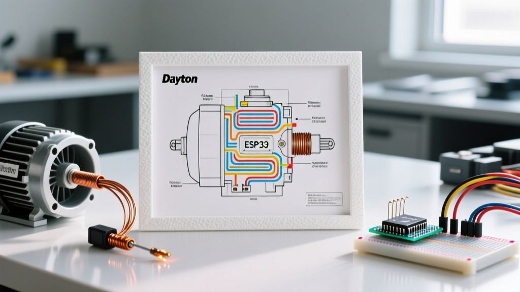
Dayton electric motors, distributed exclusively by Grainger, are the workhorses of commercial HVAC systems, industrial blowers, and air compressors. When a motor fails or behaves erratically, guessing the root cause leads to wasted time and unnecessary part replacements. The wiring diagram for Dayton electric motor models is not just an installation guide; it is a precise diagnostic map. By cross-referencing the schematic with a digital multimeter (DMM), you can isolate faults in the start winding, centrifugal switch, thermal overload protector, or capacitor circuit within minutes.
In this guide, we will dissect the schematics of Dayton's most common single-phase and three-phase models, providing actionable troubleshooting matrices and real-world failure modes observed in field applications.
Core Schematic Components & Nomenclature
Before probing terminals, you must understand the standardized symbols used in Dayton schematics. Unlike generic diagrams, Dayton prints specific terminal designations and color codes directly on the motor's wiring plate.
- L1 & L2: The primary line voltage inputs. For 115/230V dual-voltage motors, the internal coil connections change based on which terminals L1 and L2 are bonded to.
- OL (Thermal Overload): A bimetallic strip or electronic sensor embedded in the stator windings. On diagrams, it is shown in series with the main run winding.
- CS (Centrifugal Switch): A mechanical governor that disconnects the start winding once the motor reaches 75% of its rated RPM. Represented by a normally-closed switch symbol on the schematic.
- Start vs. Run Windings: The run winding (typically Black and White wires) uses thicker wire with lower resistance. The start winding (typically Red and Yellow wires) uses thinner wire with higher resistance and is only energized during startup.
Common Dayton Motor Models & 2026 Diagnostic Baselines
Different motor architectures require different troubleshooting approaches. Below is a reference table for three of the most frequently serviced Dayton motors in industrial and commercial settings.
| Dayton Model | Specs | Motor Type | Common Fault | 2026 Avg. Replacement Cost |
|---|---|---|---|---|
| 6K562 | 1/2 HP, 115/230V, 1725 RPM | Split-Phase (No Cap) | Centrifugal switch arcing | $185 (Full Motor) |
| 1T511 | 1 HP, 115/230V, 1725 RPM | Capacitor-Start | Start capacitor degradation | $22 (Dayton 2MDV6 Cap) |
| 3N442 | 2 HP, 208-230/460V, 3-Phase | 3-Phase Induction | Phase imbalance / VFD harmonics | $410 (Full Motor) |
Step-by-Step Troubleshooting Using the Diagram
Fault 1: Motor Hums but Will Not Start (Single-Phase)
This is the most common service call for Dayton capacitor-start models like the 1T511. The hum indicates the run winding is energized, but the rotating magnetic field required for startup is absent.
- Isolate Power: Follow OSHA Lockout/Tagout (LOTO) standards to ensure the circuit is de-energized and verified.
- Consult the Diagram: Locate the start capacitor and the centrifugal switch (CS) on the schematic. They are in series with the start winding.
- Test the Capacitor: Disconnect the Red and Yellow start wires. Set your DMM to capacitance (µF). A healthy Dayton 2MDV6 capacitor should read between 124µF and 149µF. If it reads below 100µF or shows an open circuit (OL), replace it.
- Check the Centrifugal Switch: If the capacitor is good, the mechanical switch may be stuck open due to dust accumulation or broken spring tension. Use the DMM continuity setting across the switch terminals. With the motor at rest, it must show continuity (near 0.0Ω).
Fault 2: Motor Starts, but Trips Thermal Overload (OL) Repeatedly
If the motor runs for 3 to 10 minutes before clicking off and requiring a cool-down period, the thermal overload protector is doing its job. The wiring diagram shows the OL in series with the main power line.
- Voltage Drop Test: Under full load, measure the voltage directly at the motor's L1 and L2 terminals. If the supply is 115V but the motor terminals read 102V, you have an 11% voltage drop. The NEMA MG 1 standard dictates that motors should operate within ±10% of rated voltage. A severe voltage drop causes amperage to spike, tripping the OL. Upsize the supply wiring.
- Ambient Temperature: Dayton motors are rated for a 40°C (104°F) maximum ambient environment. If installed in an unventilated mechanical closet exceeding this, the bimetallic OL will trip prematurely.
Fault 3: Reversing Rotation on Split-Phase Models
When installing a Dayton 6K562 on a new blower assembly, you may find the rotation is backward. The wiring diagram provides a simple solution: reverse the start winding leads relative to the run winding.
Expert Tip: Never swap the main run winding leads (Black/White) to reverse a single-phase motor. You must swap the start winding leads (Red/Yellow). If your diagram shows Red connected to L1 and Yellow to the Centrifugal Switch, reverse them so Yellow connects to L1 and Red connects to the switch.
Multimeter Diagnostic Matrix: Winding Resistance
To verify the health of the stator windings without disassembling the motor, use the wiring diagram to identify the isolated coil terminals. Set your DMM to the lowest Ohms (Ω) range. According to Fluke's motor troubleshooting guidelines, comparing the resistance ratios between windings is the fastest way to detect shorted turns.
| Test Points (Dayton 1HP Cap-Start) | Expected DMM Reading | Failure Indication |
|---|---|---|
| Run Winding (Black to White) | 1.5Ω - 3.0Ω | If 0.0Ω: Dead short. If OL: Open winding. |
| Start Winding (Red to Yellow) | 4.5Ω - 12.0Ω | Start winding should be 3x to 5x higher than run. |
| Run to Ground (Black to Chassis) | OL (Infinite) | Any reading < 2 MΩ indicates ground fault/moisture. |
| Start to Ground (Red to Chassis) | OL (Infinite) | Insulation breakdown; motor requires rewinding. |
Three-Phase Dayton Motors: Phase Imbalance & VFD Issues
For three-phase models like the Dayton 3N442, the wiring diagram will show a Wye (Y) or Delta (Δ) configuration. Troubleshooting these relies heavily on voltage and current balancing.
If a three-phase Dayton motor is overheating despite running under its rated amperage, check for phase voltage imbalance. Measure the voltage between L1-L2, L2-L3, and L1-L3. Calculate the average voltage, then find the maximum deviation from that average. A phase imbalance of just 2% can cause a 15% to 20% increase in stator heating. If the motor is driven by a Variable Frequency Drive (VFD), ensure the VFD's carrier frequency is set below 4 kHz to prevent premature insulation failure on standard Dayton inverter-duty windings.
Safety & NEC Compliance Reminders
When using any wiring diagram for Dayton electric motor installations or major rewiring, compliance with the National Electrical Code (NEC) is mandatory. Specifically, NEC Article 430 governs motor circuits, requiring inverse-time circuit breakers or time-delay fuses sized up to 250% of the motor's Full Load Amps (FLA) to accommodate the massive inrush current (Locked Rotor Amps) during startup without nuisance tripping. Always verify the FLA printed on the Dayton nameplate matches the thermal overload setting on your motor starter.
Frequently Asked Questions
Can I bypass the thermal overload protector on a Dayton motor?
Never bypass the internal thermal overload (OL). Doing so violates UL listings and NEC codes, creating a severe fire hazard. If the OL trips frequently, diagnose the root cause (overloading, low voltage, or high ambient heat) rather than defeating the safety mechanism.
Why does my Dayton motor wiring diagram show 6 wires, but I only have a 4-wire supply?
Dual-voltage (115/230V) single-phase motors utilize multiple internal coil taps. The 6 wires allow you to wire the run and start windings in parallel for 115V, or in series for 230V. Consult the specific 115V or 230V schematic block printed on the motor's junction box cover to wire-nut the unused internal taps together correctly.
How do I test a centrifugal switch if the motor is fully enclosed?
If the motor is a Totally Enclosed Fan-Cooled (TEFC) design and you cannot visually inspect the switch, rely on the wiring diagram's terminal map. Disconnect the start circuit and use a multimeter to test for continuity across the switch terminals. Manually rotate the motor shaft by hand; you should hear a distinct mechanical 'click' and see the multimeter transition from continuity to an open circuit as the shaft reaches operational speed thresholds.