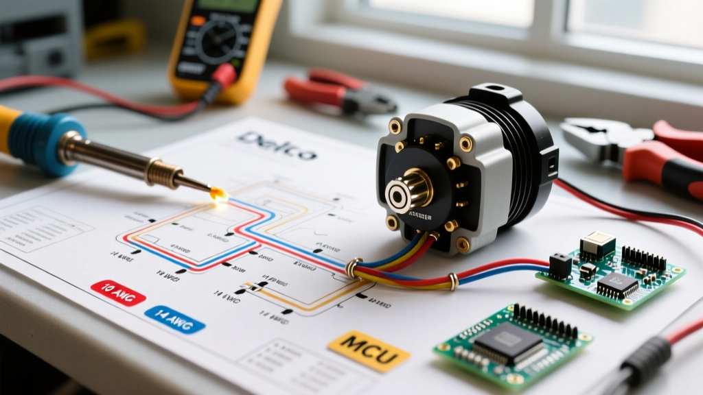

Wiring Diagram for Delco Remy Alternator: Safety & Code Compliance
When upgrading a vehicle’s charging system or restoring a classic, finding an accurate wiring diagram for Delco Remy alternator setups is only the first step. The true challenge lies in executing the installation safely and in compliance with modern electrical codes. Whether you are installing a lightweight 10SI (63A–100A) in a street rod or a heavy-duty 28SI (160A–200A) in a commercial work truck, improper wiring can lead to catastrophic electrical fires, voltage drops, and premature component failure.
As of 2026, the shift toward high-amperage accessories (electric power steering, auxiliary HVAC, and lithium battery banks) places unprecedented demand on alternators. This guide bridges the gap between standard automotive practices and strict safety codes, referencing the National Electrical Code (NEC) principles adapted for DC mobile applications and the American Boat and Yacht Council (ABYC) standards for vibration and moisture resistance.
Decoding Delco Remy Terminal Configurations
Before cutting any wire, you must identify your specific Delco Remy model. The most common DIY and light-commercial units are the 10SI and 12SI series, while heavy-duty applications utilize the 28SI and 40SI. The 10SI/12SI units typically use a 3-wire configuration, though they are frequently (and often incorrectly) converted to a 1-wire setup by aftermarket vendors.
The 3-Wire 10SI/12SI Pinout
- BAT (Output Terminal): The main power output. Requires heavy-gauge cabling directly to the battery or primary distribution bus.
- Terminal #1 (L / Lamp): Connects to the ignition switch via the dashboard indicator light. This provides the initial "excitation" current to start the charging process.
- Terminal #2 (S / Sense): The voltage sense wire. This must be routed directly to the battery positive terminal to ensure the internal regulator reads true battery voltage, not the voltage at the alternator output post.
CRITICAL SAFETY WARNING: Never route the #2 Sense wire to the BAT terminal on the back of the alternator. This is a common "shortcut" that violates basic electrical principles. If there is a 1.5V drop across the main BAT cable under load, the regulator will push 15.9V to compensate, boiling your battery electrolyte and destroying sensitive vehicle ECUs.
Code Compliance: SAE, ABYC, and NEC Standards
While the NFPA 70 (National Electrical Code) primarily governs stationary AC and DC systems, its principles regarding overcurrent protection (Article 240) and grounding (Article 250) are universally adopted by marine and heavy-transport safety inspectors. For mobile applications, we cross-reference ABYC E-11 standards for DC electrical systems on boats, which provide the most rigorous guidelines for vibration, chafe protection, and moisture ingress.
Overcurrent Protection Requirements
The most frequent code violation in alternator wiring is the omission of a main overcurrent protective device (OCPD) on the BAT wire. If the BAT cable chafes against the engine block or chassis, it will carry the full short-circuit current of the battery (often exceeding 1,000A), instantly igniting the wire insulation. You must install a fuse or circuit breaker within 7 inches of the battery positive terminal on the alternator feed wire.
Wire Gauge Selection & Fusing Matrix (2026 Data)
Selecting the correct wire gauge is not just about carrying the current; it is about limiting voltage drop to less than 3% (0.42V on a 14V system). The table below outlines the minimum requirements for popular Delco Remy models, factoring in current 2026 copper pricing and standard chassis routing lengths.
| Alternator Model | Max Output | Min Wire Gauge (AWG) | Max Run Length (ft) | Required Fuse Type | Fuse Rating |
|---|---|---|---|---|---|
| 10SI / 12SI | 100A | 2 AWG | 10 ft | ANL / Mega Fuse | 125A |
| 21SI | 160A | 1/0 AWG | 12 ft | Class T Fuse | 200A |
| 28SI | 200A | 2/0 AWG | 15 ft | Class T Fuse | 250A |
| 40SI | 300A | 4/0 AWG | 10 ft | Class T Fuse | 350A |
Note: For runs exceeding the maximum lengths listed, you must step up one wire gauge size to maintain the <3% voltage drop threshold. High-strand count marine-grade tinned copper wire (e.g., Ancor or Genuinedealz) is mandatory for environments exposed to high vibration or moisture.
Step-by-Step Compliant Wiring Procedure
Follow this procedure to ensure your installation meets both safety standards and optimal electrical performance. As of early 2026, a high-quality remanufactured 12SI costs around $110–$140, while a brand-new 28SI heavy-duty unit retails between $380 and $450. Protect this investment with proper installation techniques.
- Disconnect and Isolate: Remove the negative battery cable first. Wait 15 minutes to allow vehicle capacitors and ECU memory circuits to discharge.
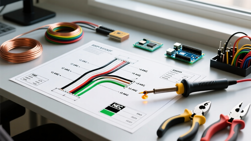
- Prepare the Main BAT Cable: Cut your 2/0 AWG (or appropriate gauge) cable. Strip the ends using a proper wire stripper to avoid nicking the copper strands, which creates localized resistance hotspots.
- Crimp and Seal: Use a heavy-duty hex-crimp tool (like the Greenlee EK425L) for the ring terminals. Apply adhesive-lined dual-wall heat shrink (3M MDT or equivalent) over the crimp barrel. When heated, the inner adhesive melts and seals out moisture, preventing the "green corrosion" that causes high-resistance failures.
- Install the Class T Fuse: Mount the fuse holder on the chassis near the battery. Connect the alternator BAT wire to the load side of the fuse, and a short jumper wire from the line side to the battery positive.
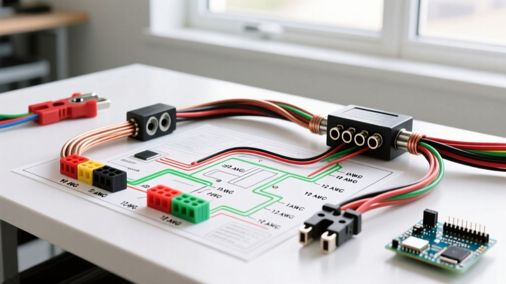
- Route the Sense Wire (#2): Use 10 AWG or 12 AWG wire. Route it away from high-tension ignition wires to prevent inductive interference. Connect it directly to the battery positive post or the main positive distribution busbar.
- Connect the Excitation Wire (#1): Run a 14 AWG wire to an ignition-switched 12V source. If using a dashboard LED instead of an incandescent bulb, you must solder a 10-ohm, 2-watt resistor in parallel to provide the necessary initial excitation current (approx. 0.5A) to "wake up" the Delco Remy regulator.
- Grounding the Case: While the alternator grounds through its mounting brackets, code-compliant heavy-duty setups require a dedicated 4 AWG ground strap from the alternator case directly to the engine block or battery negative to prevent ground-loop alternator whine in the audio system.
Common Failure Modes & Edge Cases
Even with a correct wiring diagram for Delco Remy alternator setups, real-world conditions introduce edge cases. Here is how to troubleshoot the most common compliance and performance failures.
1. Chronic Overcharging (15.2V+ at Battery)
Cause: Voltage drop on the #2 Sense wire or a blown sense-wire fuse. If the regulator reads 13.5V at the alternator post due to a bad connection, it will overcompensate.
Fix: Perform a voltage drop test. With the engine running and loads applied, measure DC voltage between the alternator case and the battery negative (should be <0.1V), and between the BAT post and battery positive (should be <0.2V). If the sense wire shows >0.1V drop, replace the wire or clean the terminal.
2. Alternator Whine in Audio Systems
Cause: Ground loop. The alternator case is grounding through the engine mounts, and the audio system is grounding to the chassis, creating a path for AC ripple current.
Fix: Install a dedicated braided copper ground strap (minimum 4 AWG) directly from the alternator mounting ear to the vehicle's main ground bus. Do not rely on painted engine blocks or rubber-isolated motor mounts for high-frequency noise dissipation.
3. Melted Connector Plugs (10SI/12SI)
Cause: Using cheap, aftermarket plastic connector pigtails with undersized brass terminals. Under high-amp loads, the resistance at the terminal generates enough heat to melt the plastic housing, shorting the sense and excitation wires.
Fix: Source OEM-grade Delphi/Aptiv connector housings and use proper terminal crimpers (not pliers). Apply dielectric grease (like Amsoil or Permatex) to the terminals before mating to prevent oxidation.
Final Inspection Checklist
Before starting the engine, verify the following:
- Main BAT fuse is installed within 7 inches of the battery positive.
- All wire looms are secured with UV-resistant zip ties, maintaining at least 2 inches of clearance from exhaust manifolds.
- Belt tension is set to the manufacturer's specification (typically 1/2 inch deflection at 90 lbs of force for V-belts; use a Krikit gauge for serpentine belts).
- Multimeter is connected to the battery terminals to verify a 13.8V to 14.4V charging curve upon startup.
For further technical specifications and warranty information on modern heavy-duty units, always consult the official Delco Remy engineering documentation. Proper adherence to these wiring and safety protocols ensures your charging system will operate reliably for hundreds of thousands of miles.