
Decoding the SAE J286 Standard: The 7-Way RV Blade
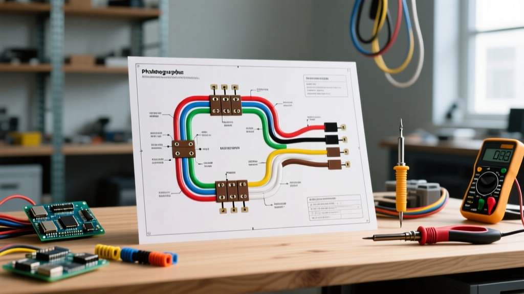
When towing heavy-duty trailers, horse trailers, or RVs exceeding 3,000 pounds, a standard 4-pin flat connector falls short. You need electric brakes, 12V auxiliary power for interior lights or winches, and reverse lockout capabilities. Before cutting a single wire or crimping a terminal, reviewing a proper wiring diagram for 7 pin trailer setups is critical to ensure your rig complies with safety standards and functions reliably on the highway.
The 7-pin RV blade connector (often referred to as a 7-way) is governed by the SAE J286 standard and RVIA (Recreation Vehicle Industry Association) guidelines. Unlike older, proprietary setups, modern 7-pin wiring follows a strict color-code and pin-assignment matrix. Below is the definitive pinout reference for both the vehicle-side socket and the trailer-side plug.
| Pin | Function | Wire Color | Minimum AWG | Circuit Notes |
|---|---|---|---|---|
| 1 | Ground (Chassis) | White | 8 AWG | Must bond directly to trailer frame; handles return current for all circuits. |
| 2 | Electric Brakes | Blue | 10 AWG | Carries up to 15A+ from the brake controller. Voltage drop here causes weak braking. |
| 3 | Tail / Running Lights | Brown | 12 AWG | Powers all clearance, marker, and tail lights. High amperage if using halogen bulbs. |
| 4 | Right Turn / Stop | Green | 12 AWG | Combined stop/turn signal for the right side of the trailer. |
| 5 | 12V Auxiliary Power | Black | 10 AWG | Constant 12V from tow vehicle battery. Used for charging breakaway batteries or interior power. |
| 6 | Left Turn / Stop | Yellow | 12 AWG | Combined stop/turn signal for the left side of the trailer. |
| 7 | Reverse Lights / Lockout | Purple (or Red) | 12 AWG | Powers reverse lamps and triggers electric brake lockout solenoids on surge brake couplers. |
Wire Gauge Selection: Preventing Voltage Drop on Long Runs
A catastrophic failure mode in DIY trailer wiring is using 14 AWG or 16 AWG wire for the entire harness to save money. According to FMCSA lighting and safety regulations, commercial and heavy-duty setups require robust conductors to prevent voltage drop and overheating.
Consider the electric brake circuit (Pin 2, Blue). A dual-axle trailer with four electric brake assemblies can draw upwards of 12 to 16 amps during a panic stop. If you run 25 feet of 14 AWG wire from the truck's brake controller to the trailer axles, you will experience a voltage drop of nearly 1.5 volts. This means your brakes only receive 10.5V instead of 12V, resulting in a 15-20% loss in braking torque. Always use 10 AWG stranded copper for the Blue (brakes) and Black (12V aux) wires, and 8 AWG for the White (ground) wire to ensure a zero-resistance return path.
Pre-Installation Planning and Tool Checklist
Do not rely on cheap, gas-station wiring kits. For a professional-grade installation in 2026, budget between $85 and $140 for high-quality materials. Your toolkit must include:
- Connectors: 10-12 AWG adhesive-lined marine heat shrink butt connectors (e.g., Wirecare or 3M FP-301). Avoid standard vinyl crimps.
- Socket/Plug: A heavy-duty metal or UV-stabilized polycarbonate 7-way plug with a spring-loaded cover (e.g., Curt 58150 or Hopkins 43385).
- Chemicals: Permatex 22058 Dielectric Grease to prevent galvanic corrosion on the blade contacts.
- Protection: Split-loom tubing (1/2 inch) and nylon cable ties with stainless steel mounting bases.
- Tools: A dedicated heat gun (not a lighter) for shrinking, a wire stripper with AWG-specific dies, and a digital multimeter.
The 4-Pin to 7-Pin Conversion Scenario
Many modern half-ton trucks (like the Ford F-150 or Chevy Silverado 1500) come from the factory with a 4-pin flat connector but lack the wiring for a 7-pin. If you are planning an upgrade, you do not need to rewire the entire truck. Instead, use a T-One vehicle wiring harness combined with a universal 7-way upgrade kit (such as the Tekonsha 3035-P or Curt 56226, typically priced around $65).
- Plug in the T-One: Insert the T-connector into the vehicle's factory tail light harness behind the rear bumper.
- Route the Auxiliary Wires: The upgrade kit will include a long run of Blue (brake) and Black (12V) wire. Route these along the driver-side frame rail, securing them every 12 inches away from the exhaust system.
- Connect to the Controller: Run the Blue wire through the firewall to your aftermarket brake controller (e.g., Tekonsha Prodigy P3 or Curt Echo). Connect the Black wire directly to the vehicle battery's positive terminal via a 30A inline circuit breaker.
Routing, Looming, and Physical Protection
The undercarriage of a trailer is a hostile environment characterized by road debris, salt, water, and extreme temperature fluctuations. When executing your wiring diagram for 7 pin trailer routing, follow these physical protection rules:
- The 18-Inch Rule: Keep all wiring at least 18 inches away from any exhaust components on the tow vehicle to prevent the wire insulation from melting and shorting against the frame.
- Grommets are Mandatory: Whenever a wire passes through a metal crossmember or the trailer tongue, use a rubber grommet. Bare metal edges will slice through wire insulation within a few hundred miles of vibration, causing a dead short.
- Drip Loops: Before the wire enters the trailer's rear junction box or light housings, create a small 'U' shaped drip loop. This prevents water from tracking down the wire directly into the light fixture or connector.
Termination: Why Vinyl Tape is Banned
Standard black vinyl electrical tape has no place in exterior automotive or trailer wiring. UV radiation and temperature swings cause the adhesive to turn into a sticky residue, eventually unspooling and exposing the copper to moisture. Instead, terminate every single splice using 3:1 adhesive-lined marine heat shrink. When heated, the inner lining melts and forms a watertight seal around the copper strands, completely blocking oxidation. For connections to the 7-way plug terminals, use ring terminals coated in dielectric grease, and torque the terminal screws to the manufacturer's specification (usually 15-20 in-lbs) to prevent loosening from highway vibration.
Expert Warning: Never rely on the hitch ball and coupler as your primary electrical ground. While metal-on-metal contact might complete the circuit temporarily, paint, rust, and grease will inevitably cause resistance. Always run the 8 AWG White ground wire from Pin 1 directly to a clean, bare-metal spot on the trailer frame, secured with a star washer and a self-tapping screw or bolt.
Common Failure Modes and Troubleshooting
Even with a perfect installation, 7-pin systems can develop faults. Here is how to diagnose the three most common issues using a multimeter and a circuit tester:
1. The 'Backfeed' Ground Loop
Symptom: When you press the brake pedal, the trailer's running lights dim, or the turn signals flash on both sides simultaneously.
Cause: The main White ground wire (Pin 1) has corroded or broken. The electrical current is seeking an alternate path to ground, 'backfeeding' through the brown tail light circuit or the turn signal circuits.
Fix: Clean the main ground connection on the trailer frame with a wire brush and sandpaper. Test continuity between Pin 1 on the plug and the trailer chassis; it should read less than 0.5 ohms.
2. Weak Electric Brakes
Symptom: The brake controller (like a Redarc Tow-Pro or Curt Discovery) shows high output, but the trailer brakes feel weak or grabby.
Cause: Voltage drop due to undersized wire (12 AWG or smaller used instead of 10 AWG) or corrosion inside the 7-way plug where the Blue wire terminates.
Fix: With the brakes manually activated via the controller slider, measure the voltage at the trailer's brake assemblies. If it reads below 11.5V, you must upgrade the Blue wire to 10 AWG or clean the plug contacts.
3. Auxiliary Battery Not Charging
Symptom: The trailer's breakaway battery or interior 12V system drains while driving.
Cause: The Black 12V auxiliary wire (Pin 5) is either not connected at the tow vehicle's battery, or the inline 30A breaker has tripped due to a short.
Fix: Check for 12.6V at Pin 5 on the vehicle-side socket with the ignition ON. If dead, trace the Black wire to the engine bay and reset or replace the thermal circuit breaker.
For further reading on commercial and heavy-duty trailer lighting compliance, refer to the etrailer 7-way connector technical guide, which provides excellent visual references for socket orientations and testing procedures. Proper planning, adherence to the SAE J286 color codes, and uncompromising termination practices will ensure your 7-pin trailer wiring survives thousands of miles of harsh towing conditions.