
Decoding the Standard Wiring Diagram for a Ceiling Fan with Light
When a ceiling fan with a light kit fails, the issue rarely lies with a burnt-out motor or a shattered bulb. In 90% of residential troubleshooting scenarios, the root cause is a misinterpretation of the manufacturer's schematic or a degraded connection at the ceiling junction box. Reading a wiring diagram for a ceiling fan with light requires understanding that you are dealing with a dual-circuit appliance sharing a single neutral return path. Whether you are working with a classic AC-motor Hunter Sea Wind or a modern DC-motor Minka-Aire with an integrated LED array, the diagnostic methodology remains rooted in isolating the line, load, and neutral conductors.
This guide bypasses generic installation advice and focuses strictly on troubleshooting existing wiring using the schematic as your diagnostic map. We will cover specific multimeter tests, modern wire connector failures, and the National Electrical Code (NEC) mandates that govern these installations.
The Core Conductors: Color Code Matrix
Before applying a multimeter, you must map the physical wires to the diagram. While the NFPA 70 National Electrical Code dictates standard premises wiring colors, appliance manufacturers use internal color codes that frequently confuse DIYers.
| Wire Color (Ceiling Box) | Wire Color (Fan Canopy) | Diagram Label | Function & Common Failure Mode |
|---|---|---|---|
| Black (or Red) | Black | L (Line) / Motor Hot | Powers the fan motor. Failure: Loose wire nut causes intermittent humming. |
| Red (or Black) | Blue | L (Line) / Light Hot | Powers the light kit. Failure: Incorrectly pigtailed to neutral, tripping breaker. |
| White | White (x2 or x3) | N (Neutral) | Shared return path. Failure: Shared neutral overload causing LED flickering. |
| Bare / Green | Green / Copper | GND (Ground) | Safety fault path. Failure: Unbonded box causing stray voltage shocks. |
Troubleshooting Scenario 1: The 'Black and Blue' Pigtail Dilemma
Symptom: The wall switch turns on the fan, but the light never illuminates. Alternatively, both turn on and off simultaneously, but you cannot control them independently.
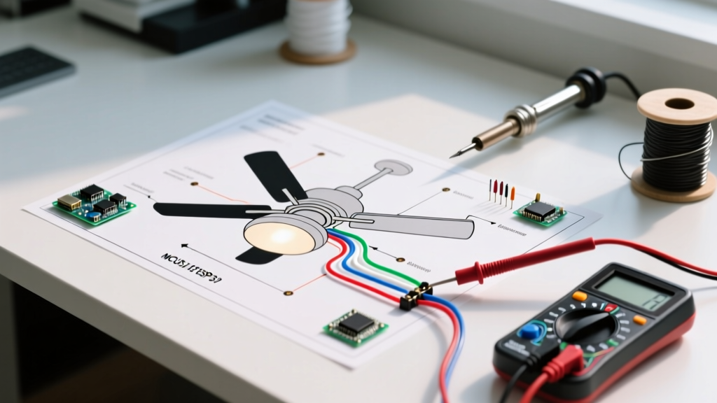
Diagram Analysis: Most modern wiring diagrams for ceiling fans with lights show two distinct hot wires entering the canopy: a Black wire (fan) and a Blue wire (light). If your ceiling junction box only has a single Black (hot) wire and a White (neutral) wire, the home was wired for a single-pole switch.
The Fix & Diagnostic Test:
- Turn off the 15A or 20A breaker at the main panel.
- Verify zero voltage using a non-contact tester like the Klein Tools NCVT-3.
- If you want the wall switch to control both the fan and light simultaneously, the diagram requires you to pigtail the fan's Black wire and the fan's Blue wire together, connecting them to the single ceiling Black wire.
- Troubleshooting Edge Case: If you have a Red AND Black wire in the ceiling box (indicating a dual-switch setup), but the light still fails, use a Fluke 117 True RMS Multimeter. Set it to AC Voltage. Place the black probe on the ceiling Red wire and the red probe on the bare ground. If you read 120V but the light is dead, the failure is internal to the light kit socket or the quick-connect Molex plug inside the fan's switch housing.
Troubleshooting Scenario 2: Bypassing the Canopy Receiver
Symptom: The fan and light are completely dead, despite verifying 120V at the ceiling junction box.
Diagram Analysis: Remote-controlled fans (such as Hampton Bay or Harbor Breeze models) utilize a canopy receiver module. The wiring diagram for these units shows the 120V AC mains entering the receiver, and low-voltage/switched outputs exiting to the motor and light. The receiver is the most common point of failure in remote-controlled units, often dying due to power surges or capacitor degradation after 5 to 7 years of use.
The Bypass Test:
- Remove the receiver module from the canopy.
- Connect the ceiling's Black (hot) wire directly to the fan's Black (motor) and Blue (light) wires using a Wago 221-412 lever connector (highly recommended over twist-on wire nuts for stranded-to-solid connections).
- Connect the ceiling White to the fan Whites.
- Restore power at the breaker.
- Result: If the fan and light turn on immediately, the receiver module is dead. You must order a replacement receiver (typically $25–$45 in 2026) matching the exact DIP switch frequency of your handheld remote. If they remain dead, the fault lies in the downrod internal wiring or the motor windings.
Troubleshooting Scenario 3: Integrated LED Driver Failures
Symptom: The light flickers, buzzes, or operates at 10% brightness, while the fan motor operates perfectly.
Diagram Analysis: Modern 2026 ceiling fans rarely use standard E26 screw-in bulbs. They feature integrated LED panels powered by a concealed DC driver. The wiring diagram will show the Blue (light hot) wire entering a small transformer box before reaching the LED array.
Diagnostic Steps:
- Check the Dimmer: Standard leading-edge dimmers (like older Lutron Diva models) are incompatible with integrated fan LED drivers. They cause severe flickering and will eventually destroy the driver's internal capacitors. Ensure the wall switch is a standard toggle, or the remote is handling the PWM dimming.
- Test the Driver Output: Disconnect the Molex plug connecting the LED panel to the driver. Set your multimeter to DC Voltage. If the driver outputs the specified DC voltage (usually 12V to 36V DC, depending on the model) but the LED panel remains dark, the LED array is burnt out. Because these are proprietary, you must contact the manufacturer for a replacement light engine kit rather than attempting to solder individual SMD LEDs.
NEC Compliance and Junction Box Ratings
When troubleshooting, you must also evaluate the physical safety of the installation. A loose connection isn't just an electrical failure; it's a fire and mechanical hazard.
Critical Safety Code: According to NEC Article 314.27, ceiling fan junction boxes must be specifically listed and marked for ceiling fan support. Standard round plastic 'pan' boxes rated only for static lighting fixtures (typically up to 50 lbs) are illegal for ceiling fan installations due to the dynamic torque and vibration generated by the motor. If your diagram troubleshooting reveals a failing, wobbling box, you must install a retrofit fan-rated brace box (like the Saf-T-Brace) before re-terminating the wires.
Furthermore, the Consumer Product Safety Commission (CPSC) notes that improper grounding of metal fan canopies leads to severe shock hazards, especially in humid environments or when users change light bulbs while the switch is hot. Always verify continuity between the fan's green ground wire and the bare copper ground in the ceiling box.
Essential Tools for Diagram-Based Troubleshooting
To properly execute the tests derived from your wiring diagram, ensure you have the following professional-grade tools:
- Fluke 117 True RMS Multimeter: Essential for accurately reading the low-voltage DC outputs of integrated LED drivers and verifying exact 120V AC line drops.
- Wago 221-412 Lever Connectors: Twist-on wire nuts frequently fail when connecting the 18 AWG stranded wire of a fan light kit to the 14 AWG solid copper of the house wiring. Lever connectors provide a permanent, vibration-proof gas-tight seal.
- Klein Tools NCVT-3 Non-Contact Voltage Tester: Crucial for verifying the absence of voltage at the canopy before touching any exposed conductors.
Frequently Asked Questions
Can I use a wall dimmer switch on the fan motor and light simultaneously?
No. Standard wall dimmers are designed strictly for resistive or compatible LED lighting loads. Sending chopped AC voltage to an inductive ceiling fan motor will cause it to overheat, hum loudly, and eventually burn out the motor windings. If your wiring diagram shows a single hot feed, use a standard single-pole switch for power, and rely on the fan's internal pull chains or remote control for speed and light dimming.
Why does the light flicker only when the fan is set to 'High'?
This indicates a voltage drop caused by a high-resistance connection on the shared neutral (White) wire. When the motor draws maximum current on the 'High' setting (typically 0.5 to 0.8 Amps for modern DC motors, up to 1.5 Amps for older AC motors), the poor neutral connection causes the voltage available to the light circuit to sag. Turn off the breaker, open the canopy, and redo the white-to-white wire nut connection, ensuring no bare copper is exposed and the stranded wire is fully seated.