
Introduction to Rocker Switch Topologies
Whether you are building a custom overhead console for an off-road vehicle, wiring a marine distribution panel, or prototyping a 120V AC DIY power tool, understanding the exact wiring diagram for rocker switch configurations is non-negotiable. Rocker switches are the industry standard for high-amperage, panel-mount applications due to their tactile feedback, dust-resistant actuator seals, and clear visual state indicators. However, the physical similarity between a basic 2-pin switch and a 3-pin illuminated switch leads to catastrophic wiring errors, blown fuses, and melted dash panels.
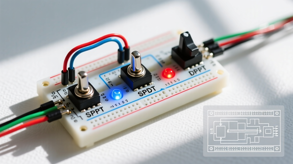
In this 2026 reference guide, we break down the exact pinouts, terminal sizing, and load-derating matrices for SPST (Single Pole Single Throw), SPDT (Single Pole Double Throw), and DPDT (Double Pole Double Throw) rocker switches. We will also address the most common failure point in modern DIY builds: improperly grounding the internal LED illumination circuit.
The Core Anatomy: Terminals and Pinouts
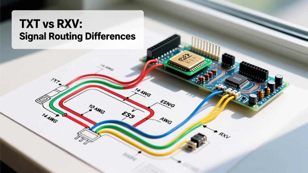
Before cutting any wire, you must identify the terminal format. The vast majority of automotive and marine rocker switches (including popular models like the Nilight 90014E and Carling V-Series) utilize .250-inch (6.35mm) FASTON quick-connect spade terminals.
- Power Source (VCC/Line): Usually labeled with an LED symbol or a specific color (often brass or copper).
- Load (Accessory): Usually silver or nickel-plated.
- Ground (LED only): Usually a smaller .110-inch spade or distinctly marked with a ground symbol.
Expert Insight: Never use bare metal crimp connectors for rocker switch terminals in metallic enclosures. Always use fully insulated nylon female spade connectors (Red for 22-18 AWG, Blue for 16-14 AWG). A loose bare spade vibrating against an aluminum dash panel will cause a dead short, potentially bypassing your inline fuse if wired incorrectly.
Standard SPST Rocker Switch Wiring Diagram (ON-OFF)
The SPST (Single Pole, Single Throw) switch is the most common topology for simple ON-OFF control of lights, winches, and auxiliary fuel pumps. However, the 3-pin illuminated SPST causes the most confusion.
The 3-Pin Illuminated SPST Pinout
If you are using a standard 12V LED rocker switch (like a generic Nilight or Carling VLD1), the pins are typically arranged as follows:
- Pin 1 (Power In): Connect to your fused 12V DC source.
- Pin 2 (Power Out / Load): Connect to the positive terminal of your accessory (e.g., LED light bar).
- Pin 3 (LED Ground): Connect directly to the chassis ground or negative bus bar.
Critical Edge Case: If you mistakenly wire Pin 3 to the Load side (Pin 2) instead of a dedicated ground, the switch's internal LED will attempt to ground through your accessory. If the accessory is a high-impedance LED light bar, the switch's internal LED will glow dimly when OFF, or the accessory will backfeed, causing ghost voltage issues in your 2026 LiFePO4 battery management systems.
SPDT (ON-ON and ON-OFF-ON) Wiring Diagram Reference
SPDT switches are required when you need to toggle between two different power sources, or control a device with two distinct states (e.g., high/low speed fans, or switching between shore power and inverter power).
Standard 3-Pin SPDT (ON-ON) Pinout
Unlike the illuminated SPST, a standard 3-pin SPDT switch does not have a ground pin. All three pins carry load or source current.
- Pin 1 (Output A): Connects to Accessory A.
- Pin 2 (Common / Source): Connects to your fused Power In.
- Pin 3 (Output B): Connects to Accessory B.
When the rocker is toggled to the top position, Pin 2 connects to Pin 1. When toggled to the bottom, Pin 2 connects to Pin 3. For a deeper understanding of mechanical switch states, refer to the SparkFun Switch Basics guide, which provides excellent visual schematics of internal contact bridging.
DPDT Configurations for Motor Reversing
A 6-pin DPDT (Double Pole, Double Throw) rocker switch, such as the heavy-duty Cole Hersee M-582, is the standard for reversing DC motors (like winches or linear actuators). By crossing the output wires (Pin 1 to Pin 6, and Pin 3 to Pin 4), you create an H-bridge circuit. Toggling the switch reverses the polarity across the motor terminals, changing the direction of rotation without requiring complex solid-state relays.
Wire Gauge and Amperage Derating Matrix
One of the most dangerous mistakes in DIY electrical builds is assuming a switch's amperage rating is universal across AC and DC voltages. DC arcs do not have a natural zero-crossing point to extinguish the spark, meaning a switch rated for 20A at 12V DC might only be safely rated for 8A at 120V AC. Always consult the NFPA 70 National Electrical Code for AC mains compliance.
| Switch Rating (DC) | Equivalent AC Rating | Max Wire Run (12V DC @ 10A) | Recommended AWG (Chassis) | Recommended AWG (Marine/Bundled) |
|---|---|---|---|---|
| 20A @ 12V DC | 10A @ 125V AC | 15 feet | 14 AWG | 12 AWG |
| 35A @ 12V DC | 15A @ 125V AC | 10 feet | 12 AWG | 10 AWG |
| 50A @ 12V DC | Not Recommended | 8 feet | 10 AWG | 8 AWG |
Note: Marine and bundled wire runs require a thicker gauge (lower AWG number) due to reduced ambient airflow and higher thermal retention, a standard strictly enforced by ABYC (American Boat & Yacht Council) guidelines.
Common Failure Modes and Troubleshooting
Even with a perfect wiring diagram for rocker switch setups, environmental and thermal factors can cause failures. Here is how to diagnose the three most common issues:
1. Thermal Melting at the FASTON Terminal
Symptom: The plastic housing around Pin 2 (Load) is warped or smells like burning ozone.
Cause: Vibration has loosened the female spade connector, increasing electrical resistance. High resistance generates localized heat (I²R losses), which melts the switch housing.
Fix: Replace the switch. Use a crimping tool with the correct die (not standard pliers) to ensure a gas-tight crimp on the spade connector, and apply dielectric grease to prevent corrosion.
2. LED Illumination Burnout
Symptom: The accessory works, but the internal switch LED is dead or flickering.
Cause: Voltage spikes from inductive loads (like relays or compressors) are back-feeding into the LED circuit. Most cheap 12V rocker switches use a simple current-limiting resistor rather than a constant-current driver.
Fix: Install a flyback diode across the coil of the relay you are switching, or upgrade to a premium switch like the Carling V-Series Contour, which features integrated transient voltage suppression.
3. Ghost Voltage and Backfeed
Symptom: An LED light bar glows faintly even when the rocker switch is in the OFF position.
Cause: The internal LED of the switch is leaking a tiny amount of current (usually 10-20mA) through the load circuit to find a ground.
Fix: Wire a 10k-ohm, 1/2-watt bleeder resistor in parallel with the load (between the positive load wire and ground) to absorb the leakage current.
Expert Sourcing and Component Recommendations
As of 2026, the market is flooded with substandard, unbranded rocker switches that fail to meet their stated amperage claims. For mission-critical applications, source your components from verified manufacturers. Littelfuse (the parent company of Carling and Cole Hersee) provides industry-leading marine and automotive switches.
- Budget / Auxiliary Lighting: Nilight 90014E 5-Pack (SPST, 12V LED, 20A). Priced around $9.99. Excellent for interior dash pods and low-duty-cycle accessories.
- Marine / High-Vibration: Carling VLD2 Contour Series (SPDT, sealed to IP68). Priced between $15.50 and $19.00 per unit. Features a matte finish that resists UV degradation and salt spray.
- Heavy Duty / Winches: Cole Hersee M-532 (SPST, 50A @ 12V). Priced around $28.00. Utilizes heavy copper contacts designed to handle the massive inrush current of DC winch motors.
FAQ: Rocker Switch Wiring Edge Cases
Q: Can I use a 12V DC illuminated rocker switch on a 24V DC system?
A: No. The internal current-limiting resistor is calculated for 12V-14.4V. Applying 24V-28V will instantly burn out the LED and potentially melt the internal lens. You must use a switch specifically rated for 24V DC, or wire an external step-down resistor.
Q: Does the orientation of the switch matter for the wiring diagram?
A: Electrically, no. Mechanically, yes. Most standard rocker switches are designed so that pressing the bottom of the actuator turns the circuit ON. If you mount the switch upside down, your ON/OFF logic will be inverted, which is a severe safety hazard in emergency shutoff scenarios.