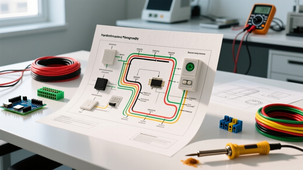

Treating Your Alarm System as a Hardwired Appliance
When homeowners and DIYers think of home appliances, they usually picture refrigerators, HVAC units, or water heaters. However, a hardwired security control panel—such as the DSC PowerSeries Neo HS2032 or the Resideo PROA7PLUS—is fundamentally a complex, hardwired appliance. It requires a dedicated high-voltage branch circuit, a step-down transformer, low-voltage signaling loops, and strict adherence to electrical codes. Understanding how to read and execute a wiring diagram for alarm systems is critical to ensuring your property is protected against intrusions and environmental hazards without suffering from false alarms or power failures.
In this comprehensive appliance wiring tutorial, we will break down the schematic anatomy of a modern hardwired alarm system. We will cover exact wire gauges, terminal configurations, End-of-Line (EOL) supervision, and the specific failure modes that occur when installers ignore the manufacturer's wiring diagrams.
Decoding the Wiring Diagram for Alarm Systems
Every professional alarm installation begins with the manufacturer's schematic. A standard wiring diagram for alarm systems is divided into three distinct subsystems:
- The Power Subsystem: High-voltage AC input, step-down transformer, and battery backup.
- The Data/Keypad Subsystem: The communication bus linking the main board to user interfaces.
- The Zone/Loop Subsystem: The sensor networks (contacts, PIRs, glass breaks) that monitor the physical environment.
NEC Compliance Note: According to the National Electrical Code (NEC), alarm system wiring must comply with NFPA 70 (Article 725 for Class 1, 2, and 3 Circuits). Low-voltage alarm wires must be physically separated from high-voltage AC wiring by at least 2 inches to prevent electromagnetic interference (EMI), which can cause data bus corruption and false alarms.
1. The Power Subsystem: Transformers and Batteries
The heart of the alarm panel is its power supply. Most standard residential panels require a 16.5VAC, 40VA step-down transformer (such as the Honeywell 1361). In 2026, with smart home integrations and cellular communicators drawing more standby current, upgrading to a 50VA transformer is highly recommended to prevent brownouts during battery charging cycles.
The transformer connects to the panel's AC terminals. Polarity does not matter here, as the panel's internal bridge rectifier converts the AC to DC. However, the 12V 7Ah Sealed Lead Acid (SLA) backup battery is strictly polarized. Connecting the red wire to the black terminal will instantly blow the panel's internal 3A automotive-style blade fuse and can permanently fry the microprocessor.
2. The Keypad Data Bus
Modern keypads communicate via a proprietary data bus. When reading the wiring diagram for alarm systems, you will typically see a 4-wire configuration for keypads:
- Red (PWR): +12VDC Auxiliary Power
- Black (COM): Ground / Negative
- Yellow (Data A / Y): Serial Data Positive
- Green (Data B / G): Serial Data Negative
Failure Mode: If the keypad powers on (screen lights up) but displays 'No Communication' or 'Module Missing', the installer has likely swapped the Yellow and Green data wires, or the run exceeds the maximum bus length without a repeater.
Wire Gauge and Selection Matrix
Selecting the correct wire gauge is where many DIY installations fail. Voltage drop over long runs will cause PIR motion sensors to trigger false alarms or fail to detect movement. Below is the 2026 standard wire selection matrix for hardwired alarm appliances.
| Subsystem | Recommended Wire Type | Gauge (AWG) | Max Run Length | Primary Use Case |
|---|---|---|---|---|
| Keypads / Data Bus | 4-Conductor Stranded | 18 AWG | 1,000 ft | Red, Black, Yellow, Green |
| Magnetic Contacts | 2-Conductor Solid/Stranded | 22 AWG or 20 AWG | 300 ft | Doors, Windows (Low Current) |
| PIR Motion Sensors | 4-Conductor Stranded | 18 AWG | 500 ft | Power + Relay Loop |
| Sirens / Strobes | 2-Conductor Stranded | 14 AWG or 16 AWG | 100 ft | High Current (Bell/Siren) |
Pro-Tip for 2026: Due to fluctuations in the global copper market, the price difference between 22 AWG and 18 AWG security wire has narrowed significantly (averaging $0.12 to $0.18 per foot). Always pull 18 AWG 4-conductor wire to every device location, even if you only need 2 wires for a basic door contact today. This future-proofs the run for wireless-to-wired converters or glass-break microphones later.
Step-by-Step Execution of the Zone Loops
The most critical part of any wiring diagram for alarm systems is the zone loop configuration. Hardwired zones operate on a supervised circuit principle. Let us walk through wiring a standard Normally Closed (NC) magnetic door contact.
Step 1: Route the Wire
Run your 18 AWG 2-conductor wire from the control panel's Zone 1 terminal and the Zone COM (Common) terminal to the door frame where the magnetic contact will be mounted.
Step 2: Wire the Sensor
Strip the jacket and connect the two wires to the screw terminals on the recessed magnetic contact. Because it is a simple NC switch, polarity does not matter at the sensor itself.
Step 3: The End-of-Line (EOL) Resistor Rule
This is the most common point of failure in amateur installations. An alarm panel does not just look for an 'open' or 'closed' circuit; it measures electrical resistance to ensure the wire hasn't been cut or tampered with. To do this, an End-of-Line (EOL) resistor must be installed.
- Honeywell / Resideo Panels: Require a 2.2kΩ resistor (Color bands: Red-Red-Red-Gold).
- DSC / Tyco Panels: Require a 5.6kΩ resistor (Color bands: Green-Blue-Red-Gold).
CRITICAL INSTALLER INSIGHT: The EOL resistor MUST be wired in series at the sensor itself, not at the control panel. If you wire the resistor at the panel terminals (a lazy shortcut some installers use to save time), the system will still function, but it will be completely blind to wire cuts. An intruder could cut the wire outside the home, and the panel would not register a tamper or fault, leaving the zone completely unprotected. Always consult the manufacturer's specific wiring diagram for alarm systems to verify EOL placement.
Troubleshooting Matrix: Common Wiring Failures
Even when following a wiring diagram for alarm systems perfectly, environmental factors and minor mistakes can cause faults. Use this diagnostic matrix to troubleshoot your hardwired appliance.
| Symptom | Probable Wiring Fault | Diagnostic Action & Solution |
|---|---|---|
| Panel reboots when siren triggers | Voltage drop on Bell circuit. 18 AWG wire is too thin for the siren's current draw (typically 300mA - 1A). | Upgrade siren wiring to 14 AWG or install a dedicated power supply module (e.g., Altronix SMP3) triggered by a relay. |
| Zone shows 'Open' when door is closed | Missing EOL resistor, or resistor value is incorrect for the specific panel brand. | Use a multimeter to measure resistance across the zone terminals at the panel. It should read ~2.2kΩ or ~5.6kΩ when the door is closed. |
| Keypad displays 'Com Error' | Data wires (Yellow/Green) routed too close to 120V AC lines, causing EMI corruption. | Reroute data bus to maintain a minimum 2-inch physical separation from high-voltage appliance wiring. |
| Panel fails to charge battery | AC transformer is underpowered (e.g., using a 20VA transformer instead of 40VA) or battery leads are reversed. | Verify transformer VA rating. Check panel charging voltage with a multimeter (should read ~13.8VDC across battery terminals). |
Integrating Life Safety and Fire Appliances
While burglar alarm zones are relatively straightforward, integrating life safety appliances like hardwired smoke detectors requires strict adherence to NFPA 72 (National Fire Alarm and Signaling Code). Standard 120V interconnected home smoke alarms cannot be wired directly into a 12V alarm panel zone.
To integrate fire safety into your alarm system wiring diagram, you must use System Sensor 4-wire low-voltage smoke detectors (like the 2W-B or i4 series). These require 12V power, ground, and a relay loop. Crucially, the wiring diagram for fire zones mandates a Normally Open (NO) configuration and requires an End-of-Line relay at the last detector to supervise the power wiring. If the power wire is cut, the relay drops out, triggering a supervisory fire trouble signal on the panel. For detailed regulations on employee and commercial alarm setups, refer to the OSHA Employee Alarm Systems standards.
Final Thoughts on Hardwired Reliability
Wireless alarm sensors have improved drastically, but a hardwired system remains the gold standard for reliability, battery longevity, and signal integrity. By treating your alarm control panel as a critical hardwired appliance, respecting wire gauge limits, and strictly following the manufacturer's wiring diagram for alarm systems—especially regarding EOL resistor placement—you will build a security infrastructure that is immune to RF jamming and battery degradation. Always power down the AC transformer and disconnect the SLA battery before making any terminal changes to prevent shorting the microprocessor.