
Mastering the Wiring Diagram for Hunter Ceiling Fan With Remote Setups
Modern Hunter ceiling fans, such as the highly popular Dempsey (Model 59264) and the Builder Elite (Model 53201), have largely phased out traditional pull-chains in favor of integrated Radio Frequency (RF) remote controls. While this offers unparalleled convenience and smart-home readiness, it introduces a critical intermediary component into your electrical topology: the canopy receiver module. If you are upgrading an older home, retrofitting a light fixture, or replacing a standard switch-operated fan, understanding the exact wiring diagram for Hunter ceiling fan with remote configurations is essential for a safe, code-compliant installation.
This comprehensive, step-by-step walkthrough will guide you through the electrical anatomy, wire matching, grounding protocols, and RF pairing processes required to get your fan and light kit operating flawlessly. As of 2026, Hunter's newer RF modules utilize advanced frequency-hopping spread spectrum (FHSS) technology to prevent cross-talk with neighboring apartments, but the fundamental hardwiring principles remain rooted in standard residential electrical practices.
Pre-Installation Safety and NEC Compliance
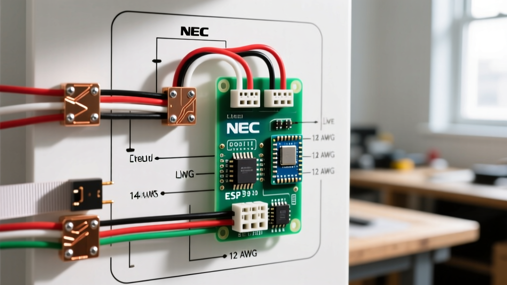
Before touching a single wire, we must address the National Electrical Code (NFPA 70) requirements for ceiling-mounted appliances. Under NEC Article 314.27, ceiling fans must be supported by a junction box specifically listed and marked as 'Acceptable for Fan Support of 35 lbs' (or up to 70 lbs for heavy-duty boxes). Standard drywall-anchor boxes or old-work light boxes will fail under the dynamic torque of a spinning fan motor, posing a severe crush hazard.
Furthermore, ensure your circuit breaker is locked out and verified dead using a Non-Contact Voltage Tester (NCVT) like the Klein Tools NCVT-1. Most residential ceiling fan circuits operate on 15-amp breakers utilizing 14 AWG solid copper wire, or 20-amp breakers utilizing 12 AWG solid copper wire. Never attempt to splice stranded appliance wire directly to solid house wire without using appropriately sized wire connectors.
Anatomy of the Hunter Canopy Receiver
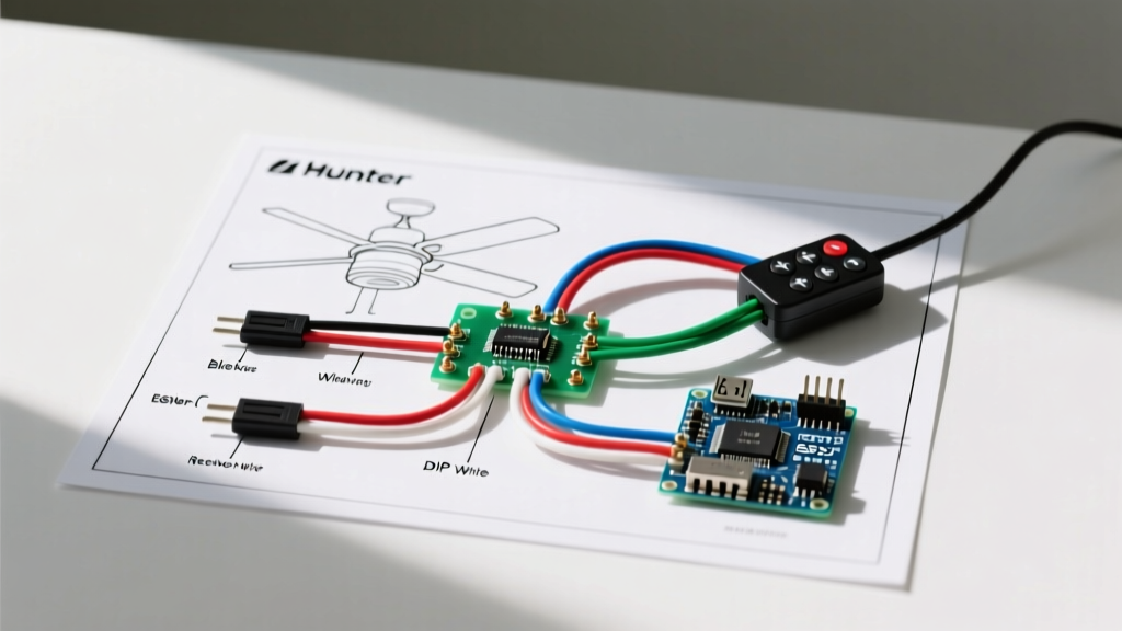
The most common receiver modules found in Hunter fan remote kits are the UC7080T (universal aftermarket style) or the proprietary Hunter SR-100 series. These modules act as a localized switch and dimmer, intercepting the constant hot feed from your ceiling and routing it to either the fan motor or the light kit based on RF commands from the handheld remote.
Wire Color Mapping Matrix
| Receiver Wire | Function | Connects To (House / Fan) | Wire Nut Recommendation |
|---|---|---|---|
| Black (Input) | AC IN L (Hot) | House Black (Ungrounded Conductor) | Ideal 33 (Orange) or Gardner Bender Blue |
| White (Input) | AC IN N (Neutral) | House White & Fan White (Common) | Ideal 33 (Orange) - 3 wire splice |
| Black (Output) | Fan Motor Power | Fan Motor Black | Gardner Bender Yellow (2 wire) |
| Blue (Output) | Light Kit Power | Fan Light Kit Blue | Gardner Bender Yellow (2 wire) |
| No Wire | Equipment Ground | House Bare/Green to Fan Green Screw | Ideal 34 (Tan) or Green Pigtail |
Step-by-Step Wiring Walkthrough
Step 1: Prep the Ceiling Junction Box
Remove the existing fixture and inspect the junction box. If you have a single hot (black), a neutral (white), and a ground (bare/green), you have a standard switch-leg setup. If your wall has a single pole switch, you will need to bypass the wall switch by wiring it to the 'ON' position permanently, or by capping the switch loop in the wall so the ceiling receives constant 120V power. The remote receiver requires constant hot to maintain its RF memory and respond to commands.
Step 2: Wire the Receiver Input to House Power
Connect the receiver's Input Black wire to the house's Black (Hot) wire. Next, connect the receiver's Input White wire to the house's White (Neutral) wire. Use a high-quality wire connector and ensure no bare copper is exposed outside the nut. Give each wire a firm 'pull test' to ensure a solid mechanical connection.
Step 3: The Grounding Bypass (Crucial Step)
A common point of confusion when reading a wiring diagram for Hunter ceiling fan with remote kits is the absence of a ground wire on the receiver module itself. The receiver is double-insulated and does not require a ground. However, the fan motor and mounting bracket absolutely do. You must splice the house ground wire directly to the fan motor's green ground screw and the green pigtail on the mounting crossbar. Do not leave the house ground floating.
Step 4: Wire the Receiver Output to the Fan
Feed the receiver's output wires down through the fan's downrod and canopy. Connect the receiver's Output Black to the fan's Black (Motor) wire. Connect the receiver's Output Blue to the fan's Blue (Light Kit) wire. Finally, splice the receiver's Output White together with the fan's White (Neutral) wire and the house's White (Neutral) wire in a single three-way junction if not already completed at the input stage (depending on canopy space, some electricians prefer to daisy-chain the neutrals inside the motor housing).
Step 5: DIP Switch Configuration and RF Pairing
Older Hunter remotes utilize physical DIP switches inside the battery compartment and on the receiver. You must match the ON/OFF pattern exactly (e.g., Up-Down-Up-Down) to ensure the remote communicates with the correct fan. For newer 2026 models utilizing rolling-code RF pairing, there are no DIP switches. Instead, restore power at the breaker, wait 30 seconds, and press and hold the 'Fan Off' and 'Light' buttons simultaneously on the remote for 5 seconds until the fan lights flash, indicating a successful digital handshake.
Pro-Tip on LED Flickering: Remote receivers utilize internal TRIAC or PWM dimming circuits. If you install aftermarket, non-dimmable LED bulbs into your Hunter light kit, you will likely experience severe strobing or a high-pitched whine. Always use Hunter's proprietary LED modules or bulbs explicitly rated for 'PWM/TRIAC Dimming' to ensure smooth 1%-100% luminance control without ghosting.
Troubleshooting Common Installation Failures
Even with a perfect wiring diagram for Hunter ceiling fan with remote execution, environmental and component variables can cause issues. Use the matrix below to diagnose post-installation anomalies.
| Symptom | Probable Cause | Technical Solution |
|---|---|---|
| Fan hums but does not spin | Blown motor capacitor or bound bearings | Locate the small black square capacitor in the switch cup. Check for bulging. Replace with identical microfarad (uF) rating. |
| Lights flicker randomly | Incompatible LED bulbs or loose neutral | Verify neutral splice integrity. Replace bulbs with Hunter OEM or CREE dimmable LEDs. |
| Remote range is under 5 feet | Antenna wire pinched or RF interference | Ensure the thin black antenna wire on the receiver is not trapped under the metal canopy or wrapped around the hot wire. |
| Fan turns on by itself | Frequency cross-talk with neighbor | Re-pair the remote using the rolling-code sequence or change the physical DIP switches to a unique pattern. |
Final Inspection and Smart Home Integration
Once the canopy is secured and the blades are balanced using Hunter's included balancing kit, test all three fan speeds and the full light dimming spectrum. For those looking to integrate their newly wired Hunter fan into a smart home ecosystem (like HomeKit or Alexa), note that standard RF remotes cannot be directly controlled by Wi-Fi hubs. You will need to install a smart ceiling fan controller (such as the Bond Bridge or a Lutron Caseta fan module) in place of, or in conjunction with, the Hunter receiver, provided your junction box has the physical depth (minimum 2.25 inches) to accommodate the extra smart relay hardware.
By strictly adhering to this wiring diagram for Hunter ceiling fan with remote configurations and respecting NEC junction box mandates, you ensure a quiet, safe, and fully functional overhead climate control system that will last for decades. For further model-specific schematics, always consult Hunter Fan Support or reference the Consumer Product Safety Commission guidelines for residential electrical appliance safety.