
Mastering the Wiring Diagram for Tankless Water Heater Installations
Transitioning from a traditional storage tank to an electric tankless water heater is one of the most demanding electrical upgrades a residential property can undergo. Unlike a standard 4,500-watt tank heater that draws roughly 18.75 amps on a single 240V circuit, high-capacity tankless units like the Stiebel Eltron Tempra 29 Plus or the EcoSmart ECO 36 can pull between 112 and 150 amps at 240V. This massive instantaneous current draw requires a meticulous, code-compliant wiring diagram for tankless water heater setups to prevent catastrophic thermal events, voltage drops, and panel fires.
As of 2026, local Authorities Having Jurisdiction (AHJs) are strictly enforcing the latest National Electrical Code (NEC) guidelines regarding high-amperage appliance branch circuits. This guide provides a deep-dive, safety-first approach to designing and executing your wiring diagram, ensuring full compliance with NEC Articles 220, 310, and 422.
Anatomy of a Code-Compliant Tankless Circuit
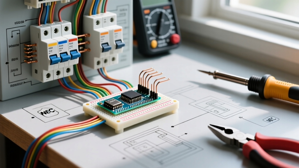
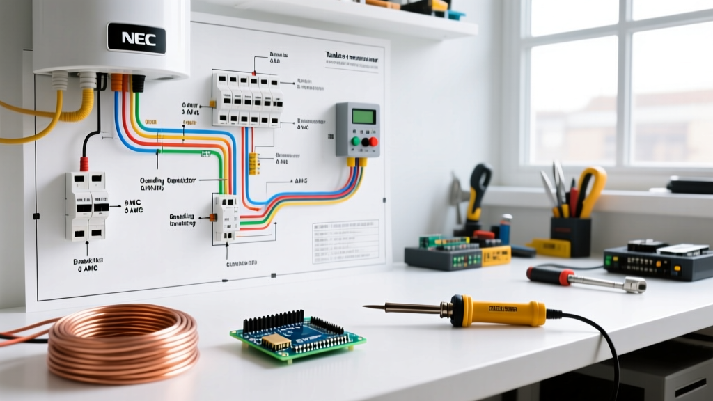
A safe wiring diagram for tankless water heater systems is not just about connecting wires to terminals; it is about managing heat dissipation, voltage drop, and fault protection. The core architecture of a compliant 240V installation includes:
- Main Service Panel or Subpanel: Must have adequate busbar capacity and physical breaker spaces.
- Overcurrent Protection Device (OCPD):strong> Correctly sized double-pole or tandem breakers.
- Branch Circuit Conductors: Properly sized copper (or specifically rated aluminum) wires with appropriate insulation ratings (THHN/THWN-2 in conduit, or NM-B for dry indoor runs).
- Service Disconnect: A readily accessible, lockable disconnect switch within sight of the appliance (NEC 422.31).
- Equipment Grounding Conductor (EGC):strong> Sized proportionally to the circuit conductors per NEC Table 250.122.
NEC Load Calculations and the 125% Rule
Under NEC Article 422, standard storage water heaters are treated as continuous loads, requiring branch circuits to be sized at 125% of the rated load. However, instantaneous (tankless) water heaters are generally classified as non-continuous loads because they do not operate at maximum current for three hours or more. Despite this, many electrical engineers and AHJs recommend applying the 125% safety margin to the main feeder calculations when adding a 36kW unit to an existing 200A residential service to account for simultaneous HVAC and EV charger usage.
Breaker and Wire Gauge Sizing Matrix
The most critical component of your wiring diagram for tankless water heater planning is matching the unit's kilowatt (kW) rating to the correct breaker and wire gauge. Undersizing wire leads to insulation meltdown; oversizing breakers defeats the overcurrent protection. Below is the definitive 2026 sizing matrix based on 240V single-phase power.
| Unit Capacity (kW) | Max Amp Draw @ 240V | Required Breaker Size | Copper Wire Size (THHN in Conduit) | Copper Wire Size (NM-B / Romex) |
|---|---|---|---|---|
| 18 kW | 75 Amps | 1 x 40A Double-Pole | #8 AWG | #6 AWG |
| 24 kW | 100 Amps | 2 x 40A Double-Pole | #8 AWG (x2 sets) | #6 AWG (x2 sets) |
| 27 kW | 112.5 Amps | 2 x 60A Double-Pole | #6 AWG (x2 sets) | #4 AWG (x2 sets) |
| 36 kW | 150 Amps | 3 x 60A Double-Pole | #6 AWG (x3 sets) | #4 AWG (x3 sets) |
Note: Most high-capacity tankless units require multiple independent branch circuits. For example, a 27kW EcoSmart ECO 27 requires three separate 40A double-pole breakers and three independent sets of #8 AWG wire. Always verify the manufacturer's specific wiring schematic, as internal terminal block configurations vary.
Step-by-Step Code-Compliant Installation Flow
Follow this sequential workflow to ensure your installation passes inspection and operates safely for decades.
Step 1: Perform a NEC Article 220 Service Load Calculation
Before pulling a single wire, verify your main service can handle the load. A 36kW tankless heater adds 150 amps of instantaneous demand. If you have a standard 200A main panel, adding a 150A load will likely trip the main breaker when the AC compressor kicks on. Upgrading to a 320A/400A Class 320 service meter base with a 200A main panel and a 125A subpanel is a common 2026 solution, costing between $2,800 and $4,500 depending on local utility trenching requirements.
Step 2: Install the Service Disconnect
NEC 422.31(B) requires a disconnecting means for motor-driven or high-amperage appliances. While a breaker in the main panel can serve as a disconnect if it is within sight and lockable, best practice dictates installing a dedicated 60A or 100A fused or non-fused AC disconnect box directly adjacent to the water heater. This allows maintenance personnel to kill power locally without navigating to a crowded subpanel.
Step 3: Route Conductors and Manage Conduit Fill
When using THHN/THWN-2 conductors in EMT (Electrical Metallic Tubing) or PVC conduit, you must adhere to NEC Chapter 9, Table 1 for conduit fill. For three current-carrying conductors plus a ground, you cannot exceed 40% conduit fill. If you are running three separate 240V circuits (6 hot wires) in a single conduit to feed a 36kW unit, NEC 310.15(C)(1) requires you to apply a 74% ampacity derating factor. This means your #6 AWG wire (rated 75A at 90°C) is derated to 55.5A, which is safely above the 60A breaker limit, but #8 AWG would fail inspection.
Critical Safety Codes: Torque and Terminations
The most frequently overlooked safety hazard in DIY and even some professional tankless installations is improper terminal torque. Loose connections create high-resistance points, leading to arc faults and thermal runaway.
NEC 110.14(D) Mandate: "Termination provisions of equipment for circuits rated 100 amperes or less, or marked for 14 through 1 AWG conductors, shall be used only for one of the following: (1) Conductors rated 60°C. (2) Conductors with higher temperature ratings, provided the ampacity of such conductors is determined based on the 60°C ampacity..." Furthermore, listed torque specifications must be strictly followed using a calibrated torque screwdriver or torque wrench.
For most Stiebel Eltron and Rheem terminal blocks, the required torque is between 25 and 35 inch-pounds. Guessing the tightness by hand is a direct code violation and a primary cause of post-installation fires. Always use a digital torque adapter.
GFCI and AFCI Requirements for 2026
Do tankless water heaters require Ground Fault Circuit Interrupter (GFCI) or Arc Fault Circuit Interrupter (AFCI) protection?
- AFCI: Under NEC 211.12, AFCI protection is generally required for all 120V, single-phase, 15- and 20-amp branch circuits supplying outlets in residential living spaces. Because tankless water heaters operate on dedicated 240V circuits of 40A or higher, they are exempt from AFCI requirements.
- GFCI: NEC 210.8(F) requires GFCI protection for outdoor receptacles and specific damp locations. If your tankless unit is installed indoors (e.g., a basement or utility closet), standard thermal-magnetic breakers are compliant. However, if the unit is mounted in an exterior enclosure or a location classified as a damp/wet area by your local AHJ, a 240V GFCI breaker (which costs upwards of $180 per pole) may be mandated.
Common Edge Cases and Failure Modes
Even with a perfect wiring diagram for tankless water heater layouts, field conditions can introduce dangerous variables. Watch for these specific failure modes:
- Aluminum Wire Oxidation: If your main panel uses aluminum busbars or you are utilizing SER aluminum cable for the feeder, you must apply an anti-oxidant compound like Noalox to the wire strands before termination. Failure to do so results in galvanic corrosion, increasing resistance and generating severe heat over 12 to 18 months.
- Shared Neutrals in Multi-Wire Branch Circuits (MWBC): Tankless heaters are strictly 240V loads and do not utilize a neutral wire. Never attempt to share a neutral from an adjacent 120V circuit in the same conduit, as the induced electromagnetic fields from 150A of tankless current will induce dangerous voltages on adjacent neutrals.
- Voltage Drop Over Long Runs: If your subpanel is located more than 100 feet from the water heater, NEC 310.15(B) recommends limiting voltage drop to 3%. For a 27kW unit drawing 112A over 150 feet, you must upsize from #6 AWG to #3 AWG copper to prevent the unit's internal flow computers from throwing low-voltage error codes.
Final Inspection and Commissioning
Before energizing the system, perform a dead-front continuity test on the equipment grounding conductor using a digital multimeter. Verify that the resistance between the unit's copper chassis and the main panel's ground busbar is less than 0.5 ohms. Once verified, energize the breakers sequentially, check the voltage at the unit's terminal blocks (it should read between 235V and 245V), and purge the water lines to remove air before turning on the heating elements. For further reading on appliance safety and efficiency standards, refer to the NFPA National Electrical Code guidelines and the Department of Energy's Tankless Water Heater documentation. For specific terminal configurations, always consult the manufacturer's official installation manuals.