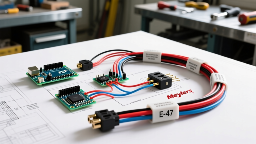

The Ultimate Wiring Diagram for a Meyers Snow Plow: E-47 and E-57 Systems
When winter hits, a reliable snow plow is the difference between a cleared driveway and a stranded vehicle. For DIY mechanics and fleet owners alike, understanding the wiring diagram for a Meyers snow plow is critical. The legendary Meyers E-47 and E-57 hydraulic pumps remain the workhorses of the industry, but their electrical systems are where 90% of field failures occur. A poorly executed wiring job leads to sluggish hydraulics, burnt-out motors, and clicking solenoids.
In this comprehensive 2026 walkthrough, we will dissect the standard 2-plug Meyers electrical architecture. We will cover high-current power routing, precision grounding, control circuit integration, and the most common failure modes you must avoid.
Required Components and 2026 Pricing Estimates
Before cutting a single wire, verify you have the correct heavy-duty components. Using standard automotive wire instead of fine-strand welding cable is a rookie mistake that leads to brittle fractures in sub-zero temperatures.
| Component | Meyers / OEM Part Number | Wire Gauge Required | Est. Cost (2026) |
|---|---|---|---|
| Hydraulic Motor (Prestolite) | 1101192 | 2 AWG Fine-Strand | $185 - $240 |
| Solenoid (Intermittent Duty) | 15193 (or Trombetta 684) | 2 AWG Fine-Strand | $45 - $75 |
| Main Power Harness | 13042 (2-Plug Kit) | 2 AWG (Power), 14 AWG (Control) | $130 - $160 |
| Adhesive-Lined Heat Shrink | N/A (3M or equivalent) | Fits 2 AWG to 14 AWG | $25 - $40 |
Phase 1: The High-Current Power Circuit
The hydraulic motor on a Meyers E-47 draws between 120 and 180 amps under peak load (such as when lifting a full blade of heavy, wet snow). Your wiring diagram must prioritize minimizing voltage drop across the main power loop.
Step 1: Battery to Solenoid Routing
- Disconnect the Vehicle Battery: Always start by removing the negative terminal to prevent dead shorts while routing the 2 AWG positive cable.
- Install the Mega-Fuse: Within 12 inches of the vehicle's positive battery terminal, install an inline 250-amp Mega-Fuse holder. This protects the truck from a catastrophic short if the plow cable chafes against the frame.
- Route the 2 AWG Positive Cable: Run the heavy-gauge red cable from the battery to the plow solenoid's primary 'BAT' terminal. Expert Tip: Keep this cable away from the exhaust manifold and steering shaft. Use split-loom tubing and zip-ties every 12 inches to prevent vibration-induced chafing.
- Crimp and Seal: Use a hex-crimp tool (not standard pliers) for your 2 AWG ring terminals. Slide adhesive-lined heat shrink over the joint and apply heat until the adhesive oozes out the ends, creating a waterproof seal against road salt.
Step 2: Solenoid to Motor Connection
Connect a second 2 AWG red cable from the solenoid's 'MOT' (Motor) terminal to the positive stud on the Meyers Prestolite hydraulic motor. Ensure the solenoid is mounted vertically if possible; Trombetta and White-Rodgers solenoids experience less internal corrosion when mounted upright, preventing moisture from pooling around the plunger.
Phase 2: The Ground Circuit (The #1 Failure Point)
"Over 75% of Meyers plow electrical issues brought into our shop are not bad motors or solenoids, but inadequate ground paths. The return path is just as critical as the supply path." — SnowPlowNews Industry Guidelines
Step 3: Establishing the Motor Ground
Do not rely on the physical mount of the hydraulic motor to the pump housing for your electrical ground. Vibration and paint will create high resistance.
- Attach a dedicated 2 AWG black ground wire directly to the ground bolt on the motor casing.
- Route this cable to the vehicle's engine block. Never ground to the alternator bracket, cylinder head, or aluminum intake manifold. The engine block provides the most direct, high-amperage path back to the battery's negative terminal.
- Clean the grounding surface on the engine block down to bare metal using a wire wheel, apply a thin coat of dielectric grease to prevent oxidation, and torque the bolt to factory specifications.
Step 4: The Solenoid Ground (Control Side)
The solenoid requires a secondary, smaller ground wire (usually 14 AWG black) to complete the electromagnetic coil circuit. This wire typically routes back to the cab control harness or directly to the vehicle chassis. Ensure the chassis ground point is free of powder coating or rust.
Phase 3: The Control and Lighting Harness
The standard Meyers 2-plug system separates the high-amperage motor power from the low-amperage control and lighting circuits. The second plug (usually a 9-pin or 12-pin connector) handles the solenoid trigger and the plow lighting.
Step 5: Wiring the Solenoid Trigger
The solenoid's 'S' (Signal) terminal requires a 12V trigger to close the high-current contacts. In the Meyers wiring diagram, this is typically the white wire from the cab control harness. When you press the 'Raise' button on the in-cab controller, it sends 12V down this white wire. Note: If your solenoid clicks but the motor doesn't spin, the issue is rarely the trigger wire; it is almost always high resistance on the main 2 AWG power or ground cables.
Step 6: Integrating Plow Lighting (FMVSS 108 Compliance)
According to federal motor vehicle safety standards, your plow's headlights, turn signals, and marker lights must sync seamlessly with the truck. As noted in the etrailer Wiring FAQ, modern vehicles use multiplexed CAN-bus systems that will throw dashboard error codes if they detect the extra resistance of plow lights.
- Use Isolation Modules: If you are wiring a 2018 or newer truck, you must use a solid-state isolation module (like the Meyers Pro-Touch or Ultramount adapters) rather than hard-splicing into the truck's headlight wires.
- LED Upgrades: If you've upgraded your plow to LED headlights, ensure your isolation module is LED-compatible. Standard halogen relays will hyper-flash or fail to trigger with low-draw LEDs.
Advanced Troubleshooting: Voltage Drop Testing
When following a wiring diagram for a Meyers snow plow, visual inspection isn't enough. You must perform a voltage drop test under load. For deeper diagnostic manuals, refer to the Meyer Products Official Support portal.
How to Perform the Test
- Set your digital multimeter to DC Volts.
- Have an assistant press the 'Raise' button in the cab while the plow is resting on the ground (creating maximum amp draw).
- Place the red probe on the battery positive terminal and the black probe on the solenoid 'BAT' terminal. A reading above 0.2V indicates a failing cable, bad crimp, or corroded fuse.
- Move the probes to the solenoid 'BAT' and 'MOT' terminals. A reading above 0.5V means the internal contacts of the solenoid are pitted and the solenoid must be replaced.
- Test the ground side: Place the red probe on the motor casing and the black probe on the battery negative terminal. Anything over 0.2V requires you to rebuild your ground strap.
Common Failure Modes to Watch For
- The 'Click-Click-Click' Death Rattle: The solenoid engages, but the voltage drop is so severe that the system voltage falls below 9V, causing the cab controller to reboot and drop the trigger signal. The solenoid opens, voltage recovers, and the cycle repeats. Fix: Upgrade to 1/0 AWG welding cable and clean all grounds.
- Melted 2-Plug Connectors: The control plug melts due to water intrusion and galvanic corrosion. Fix: Always pack the female cavities with dielectric grease and use a protective silicone boot. Never leave the plugs disconnected and exposed to the elements during the off-season.
- Pump Runs but Won't Drop: This is a hydraulic valve issue, not an electrical one, but often misdiagnosed as a wiring fault. If the motor runs but the blade doesn't move, check the 'B' and 'C' valve coils for 12V. If they have power but no magnetic pull, the coils are burnt out internally.
Final Thoughts on Meyers Plow Wiring
Wiring a Meyers snow plow requires respect for high-amperage DC circuits. By strictly adhering to the correct wire gauges, utilizing adhesive-lined heat shrink, and prioritizing a flawless engine-block ground, your E-47 or E-57 system will reliably push snow for decades. Always double-check your connections against the official schematics before applying power, and test your voltage drops before the first blizzard arrives.