
Decoding the Basic Wiring Diagram for a House
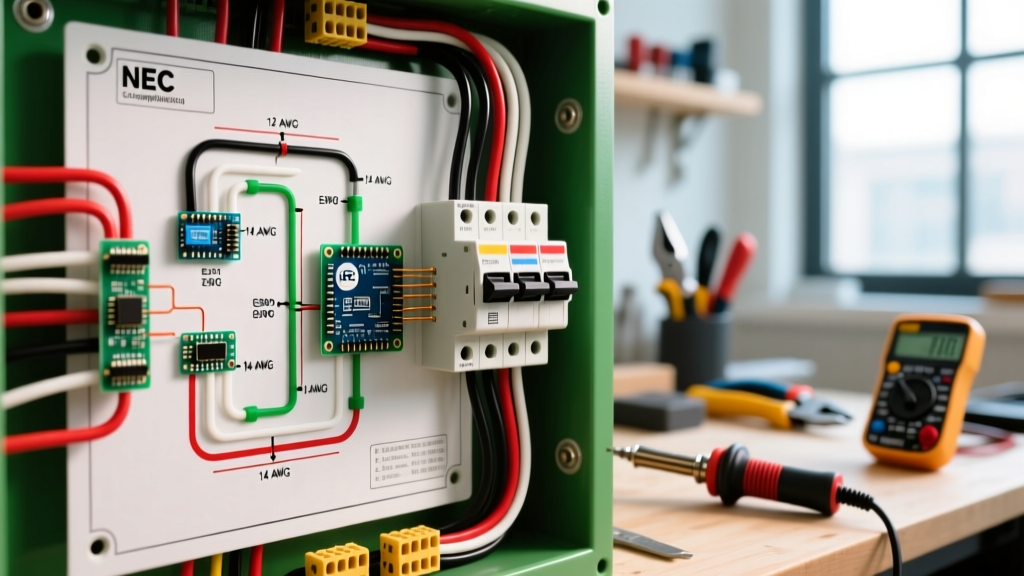
When electricians and advanced DIYers look at a basic wiring diagram for a house, they aren't just looking at lines connecting a panel to a receptacle. They are reading a strict, code-compliant map of wire gauges, insulation types, and color codes dictated by the National Electrical Code (NEC). A residential blueprint might show a simple line from the breaker box to a kitchen island, but the actual execution requires a deep understanding of ampacity derating, voltage drop limits, and proper conductor identification.
Whether you are planning a whole-home rewire, adding a subpanel, or troubleshooting an existing circuit, understanding the foundational rules of gauge sizing and color coding is non-negotiable. According to the National Fire Protection Association (NFPA), electrical failures or malfunctions are consistently among the leading causes of home structure fires. This guide breaks down the technical realities behind residential wiring diagrams, moving beyond basic theory into actionable, code-compliant execution.
The Anatomy of Residential Branch Circuits
A standard house wiring diagram divides the electrical load into distinct branch circuits. In modern residential construction, the dominant cable type for interior dry locations is Nonmetallic-Sheathed Cable, universally known by the brand name Romex (NM-B). For wet locations or underground runs, diagrams will specify UF-B (Underground Feeder) or individual THWN-2 conductors inside PVC or rigid metal conduit.
Every circuit on your diagram must be matched to a specific Overcurrent Protective Device (OCPD)—the circuit breaker. The breaker's primary job is not to protect the appliance; it is to protect the wire from overheating and catching fire inside the walls. Therefore, the wire gauge must always be sized to handle the breaker's maximum amperage, adjusted for ambient temperature and bundling factors.
NEC Wire Gauge Sizing Matrix (Copper Conductors)
The following matrix outlines the standard American Wire Gauge (AWG) sizes used in residential diagrams, mapped to their maximum ampacities and standard applications. This data is derived from NEC Table 310.16 for copper conductors.
| Wire Gauge (AWG) | Max Ampacity (60°C Column) | Standard Breaker Size | Common Residential Application |
|---|---|---|---|
| 14 AWG | 15 Amps | 15A | General lighting, bedroom/bathroom receptacles |
| 12 AWG | 20 Amps | 20A | Kitchen small appliance, dining, laundry, garage |
| 10 AWG | 30 Amps | 30A | Electric water heaters, window AC units, dryers (gas) |
| 8 AWG | 40 Amps | 40A | Electric ranges (smaller models), EV chargers (Level 2) |
| 6 AWG | 55 Amps | 50A or 60A* | Subpanels, large electric ranges, hot tubs |
| 4 AWG | 70 Amps | 70A | Large subpanels, heavy-duty workshop equipment |
| 2 AWG | 95 Amps | 100A | Main service entrance feeders (100A service) |
*Note: NEC 240.4(B) allows the next standard size up for OCPD if the ampacity does not correspond to a standard breaker size, provided it is under 800A. However, 6 AWG copper is typically limited to a 60A breaker in residential NM-B applications.
CRITICAL E-E-A-T INSIGHT: The 60°C Rule for NM-B Cable
Many DIYers look at the THHN wires inside a Romex jacket and see a 90°C rating on the insulation. However, OSHA and NEC enforcement guidelines strictly point to NEC Article 334.80: The ampacity of NM-B cable must be determined using the 60°C column of Table 310.16, regardless of the conductor's higher temperature rating. You cannot use the 90°C column for final ampacity sizing in standard residential Romex runs; it is only permitted for ambient temperature derating calculations.
Standard Color Codes and Re-Identification Rules
A proper wiring diagram relies on a universal color language to ensure safety during installation and future troubleshooting. Misidentifying a conductor is a primary cause of lethal shock hazards.
The Primary Color Palette
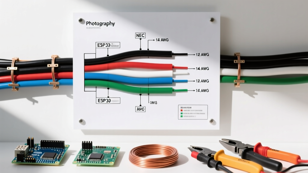
- Black & Red (Hot/Ungrounded): These carry the live current from the breaker to the device. In a 240V circuit (like a baseboard heater), both black and red are hot, each carrying 120V relative to ground.
- White or Gray (Neutral/Grounded): The current return path back to the panel. The neutral is bonded to ground only at the main service disconnect. It must never be used as a ground wire.
- Bare Copper or Green (Equipment Ground): The safety path. It carries current only during a fault condition, tripping the breaker by providing a low-resistance path back to the source.
The Switch Loop Exception (NEC 200.7)
Historically, electricians used 2-wire NM-B (Black, White, Bare) to run a switch loop to a ceiling light. The white wire was used as the hot feed down to the switch, and the black wire returned the switched hot up to the light. Under modern NEC rules, if a white wire is used as an ungrounded (hot) conductor, it must be permanently re-identified with black tape, paint, or heat shrink at both ends of the run. Furthermore, modern diagrams now require 3-wire cable (Black, Red, White, Bare) to switch loops to ensure a dedicated neutral is present at the switch box for smart switches and timers.
Voltage Drop: The Hidden Diagram Variable
Most basic wiring diagrams fail to account for distance. If your diagram shows a 12 AWG wire on a 20A circuit running to a detached garage 150 feet away, the circuit will technically pass inspection for ampacity, but it will suffer from severe voltage drop.
The NEC recommends (via Informational Notes in Article 210.19) a maximum voltage drop of 3% for branch circuits and 5% total for feeder and branch circuits combined. For a 120V circuit, a 3% drop means you can lose a maximum of 3.6 volts.
Real-World Calculation Example
Suppose you are wiring a dedicated 15A receptacle at the end of a 120-foot run using 14 AWG copper.
- Formula: VD = (2 x L x I x R) / 1000
- Variables: L = 120ft, I = 15A, R = 3.14 ohms/kft (for 14 AWG)
- Result: (2 x 120 x 15 x 3.14) / 1000 = 11.3 Volts dropped
An 11.3V drop on a 120V circuit is nearly 10%, which will cause motors to overheat and lights to dim. The solution dictated by an engineered diagram? Upsize the wire to 10 AWG or even 8 AWG to compensate for the distance, even though the breaker remains 15A.
Edge Cases: Multi-Wire Branch Circuits (MWBC)
When reading a commercial or high-end residential diagram, you will frequently encounter MWBCs. This setup uses two hot wires (Black and Red) sharing a single neutral (White) on a 120/240V split-phase system. It effectively provides two 20A circuits using only three conductors, saving copper and conduit space.
The Danger: If the two hot wires are accidentally placed on the same phase in the breaker panel, the shared neutral will carry the sum of both currents (e.g., 40A) instead of the difference, leading to an immediate neutral overload and potential fire. Modern NEC (Article 210.4) mandates that MWBCs must have a simultaneous disconnect mechanism—meaning you must use a handle-tied double-pole breaker or a tandem breaker with an identified handle tie to ensure both circuits are killed at the same time for safe maintenance.
Torque Specifications: The Final Diagram Requirement
A wiring diagram tells you where the wire goes, but it doesn't tell you how tight to secure it. Since the 2017 NEC update (Article 110.14(D)), electricians are legally required to use a calibrated torque screwdriver or wrench to tighten terminal lugs to the manufacturer's specified inch-pound (in-lb) rating. Over-tightening strips aluminum bus bars and snaps copper strands; under-tightening creates high-resistance connections that arc and melt. Always check the breaker or receptacle spec sheet—most standard 15A/20A receptacles require between 12 to 14 in-lbs of torque.
Frequently Asked Questions
Can I use 12 AWG wire on a 15 Amp breaker?
Yes. NEC Article 240.4 allows you to use a larger wire on a smaller breaker. In fact, many professional electricians exclusively use 12 AWG for all general-purpose 15A and 20A receptacle circuits to reduce voltage drop and provide a safer thermal margin, reserving 14 AWG strictly for 3-way switch loops and low-draw lighting circuits.
Why does my diagram specify AFCI/GFCI combination breakers?
Modern NEC updates require both Arc Fault (AFCI) and Ground Fault (GFCI) protection for almost all living spaces. Kitchens, bathrooms, and laundry rooms require GFCI for shock protection, while bedrooms and living rooms require AFCI for fire protection. Combination breakers provide both in a single package at the panel, eliminating the need for bulky GFCI receptacles at the first outlet in the chain.
Is aluminum wire still used in house wiring diagrams?
For branch circuits (15A-20A), copper is the undisputed standard due to the historical failures of 1970s-era AA-1350 aluminum branch wiring. However, for large feeder cables (e.g., 2 AWG to 4/0 AWG running from the meter to the main panel or to a subpanel), modern AA-8000 series aluminum alloy wire is heavily specified in diagrams. It is significantly cheaper and lighter than copper, provided the terminals are rated for aluminum (marked AL/CU) and anti-oxidant paste is applied.