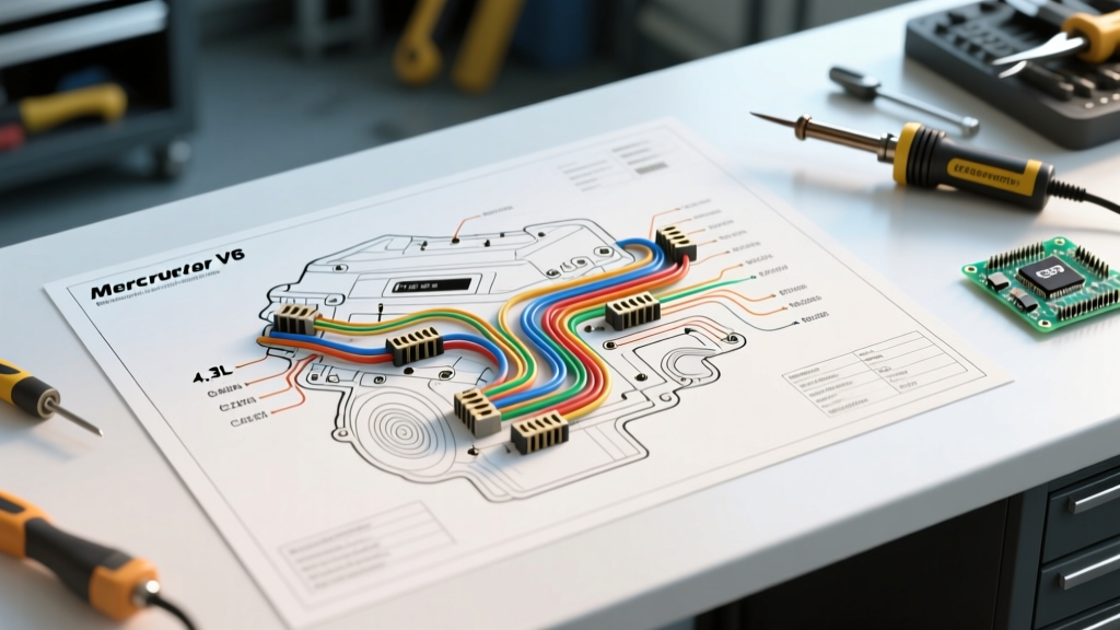

Why the Wiring Diagram for 4.3 Mercruiser Engines is Your Best Diagnostic Tool
The MerCruiser 4.3L V6 is a legendary staple of recreational boating, prized for its balance of torque and compact engine bay footprint. However, when electrical gremlins strike—manifesting as a no-crank condition, a dead alternator, or an erratic fuel pump—guessing is a fast track to a sunken weekend budget. As of 2026, a complete OEM replacement wiring harness for a 4.3L MPI (Multiport Fuel Injection) engine routinely exceeds $450, not including dealership labor rates. This makes pinpoint multimeter diagnostics, guided by the factory schematic, the most cost-effective and reliable repair strategy.
When you pull up the wiring diagram for 4.3 Mercruiser engines, you are looking at a standardized color-coded matrix governed by marine electrical standards. Unlike automotive systems, marine harnesses must account for constant high-humidity exposure, vibration, and strict galvanic corrosion prevention. According to the American Boat & Yacht Council (ABYC) E-11 standard for DC electrical systems, all conductors must be tinned copper and circuits must feature specific overcurrent protection. Understanding how to translate the schematic's lines and nodes into real-world voltage drop tests is the hallmark of a master marine technician.
Decoding the MerCruiser 4.3L Color Code Matrix
Before unbolting a single terminal, you must understand the primary conductors leaving the engine-mounted 10-pin or 14-pin cannon plug. The wiring diagram for 4.3 Mercruiser models relies on a strict color-coding convention. Below is the critical reference matrix for the primary harness.
| Wire Color | Circuit Function | Expected Voltage (Key ON) | Common Failure Mode |
|---|---|---|---|
| Purple | Ignition / ECM Wake-up | 12.0V - 12.6V | Corrosion at 10-pin cannon plug |
| Red/Purple | Fused B+ (Accessories/ECM Memory) | Battery Voltage (Constant) | Blown 20A inline fuse or chafing |
| Yellow/Red | Starter Solenoid (Crank Trigger) | 10.5V+ (Only during crank) | Shift interrupt switch misalignment |
| Pink | Fuel Level Sender Signal | 0.5V (Empty) - 3.5V (Full) | Ground fault at sender ring terminal |
| Dark Blue | Oil Pressure Sender Signal | Variable Resistance (0-160 Ohms) | Sender diaphragm rupture leaking oil |
| Black/Yellow | Ignition Kill / Ground to Stop | Open Circuit (Running) | Lanyard switch shorting to ground |
Step-by-Step Troubleshooting: The 'No-Crank' Scenario
The most common reason boaters consult the wiring diagram for 4.3 Mercruiser engines is a failure to crank. Do not immediately condemn the starter motor. Follow this voltage-drop sequence using a digital multimeter (a Fluke 87V MAX, currently retailing around $380, is the marine industry standard for its IP67 waterproof rating).
Phase 1: Battery and Main Ground Validation
- Static Voltage Check: Measure across the battery posts. You need a minimum of 12.4V. If it reads 11.8V, your starter solenoid will physically click, but the ECM will trigger a low-voltage lockout, preventing the fuel pump relay from engaging.
- Positive Voltage Drop: Set your meter to DC Volts. Place the red lead on the battery positive post and the black lead on the starter solenoid's main B+ stud. Have an assistant turn the key to START. A reading above 0.5V indicates high resistance in the positive cable or the main 150A circuit breaker.
- Negative Voltage Drop: Place the red lead on the battery negative post and the black lead on the engine block casting (not the starter housing). Crank the engine. A reading above 0.2V means your 1/0 AWG main ground strap is compromised. Clean the transom ground stud with a wire brush and apply dielectric grease.
Phase 2: The 10-Pin Cannon Plug Bottleneck
The cannon plug connects the engine harness to the helm. Moisture intrusion here is notorious. Disconnect the plug and inspect the pins. The Purple wire (Pin C on most 10-pin configurations) carries the 12V ignition switch signal to the ECM and ignition module. If this pin is green with copper chloride corrosion, the ECM never wakes up, and the starter relay will not receive the crank signal.
Phase 3: Neutral Safety and Shift Interrupt Isolation
If the Purple wire has 12V at the helm side of the plug, but the Yellow/Red wire at the starter solenoid 'S' terminal receives zero voltage during cranking, the fault lies in the safety interlocks.
Pro-Tip: Bypassing the Shift Interrupt for Diagnostics
The MerCruiser Alpha One and Bravo One outdrives utilize a shift interrupt microswitch. This switch intentionally grounds the ignition module to kill the engine momentarily, relieving gear dog pressure so you can shift. If the switch is misadjusted or the plunger is stuck, it will break the starter solenoid circuit. To test, locate the two-wire harness (usually Tan/White and Purple/White) near the shift cable anchor. Disconnect it and use a jumper wire to bypass the circuit temporarily. If the engine cranks immediately, your shift cable adjustment is out of spec, or the microswitch plunger is seized.
Charging System Diagnostics: Alternator to ECM
Modern 4.3L MPI engines utilize a Delco-style internally regulated alternator, often controlled or monitored by the Engine Control Module (ECM). A common misdiagnosis is replacing a perfectly good alternator when the actual fault is a broken 'Sense' wire.
According to Mercury Marine's official service documentation, the alternator requires a reference voltage to know how much to charge. On the 4.3L harness, this is typically a Red/Purple or solid Purple wire routed from the alternator's 'S' terminal back to the main 12V bus or ECM. If this sense wire is broken or corroded at the cannon plug, the alternator reads 0V on the sense circuit and defaults to a limp-mode output of roughly 12.8V—enough to keep the engine running, but insufficient to charge the battery or run the livewell pumps. Always verify the sense wire voltage at the alternator plug with the engine running at 2000 RPM; it must match the battery post voltage within 0.1V.
MPI vs. TKS Carbureted: Harness Architecture Differences
When sourcing a wiring diagram for 4.3 Mercruiser engines, you must verify your fuel delivery system. The harness architecture differs wildly between the two primary variants:
- 4.3L MPI (Multiport Fuel Injection): Features a high-pressure fuel pump circuit. The ECM triggers a fuel pump relay via a dedicated ground wire (often Dark Green/White). The harness includes shielded twisted-pair wiring for the Crankshaft Position Sensor (CKP) and MAP sensor to prevent electromagnetic interference (EMI) from the ignition coils.
- 4.3L TKS (Two-Barrel Carburetor) / Thunderbolt IV: A much simpler harness. It includes a dedicated Purple wire for the electric choke cap. A frequent failure point here is the choke wire losing 12V, causing the choke flap to remain closed on a warm engine, resulting in severe flooding and a no-start condition. It also relies on a standalone ignition module rather than a centralized ECM.
Essential Tools & Reference Standards
To properly execute these tests, standard automotive tools fall short in a marine environment. BoatUS marine electrical guidelines heavily emphasize using marine-specific consumables and diagnostic gear.
- Wire Tracer/Tone Generator: Essential for tracking the Pink fuel sender wire through the bilge when the gauge reads empty despite a full tank.
- Marine-Grade Heat Shrink: Never use standard electrical tape in a bilge. Use 3M adhesive-lined marine heat shrink (approx. $18 for a 50-piece kit) to seal any splice. The adhesive melts and creates a waterproof barrier against salt air.
- Dielectric Grease: Apply liberally to the cannon plug pins and the alternator connector to prevent galvanic corrosion between dissimilar metals.
Frequently Asked Questions
Can I use standard automotive copper wire for repairs?
No. The ABYC E-11 standard strictly mandates the use of tinned copper wire for marine applications. Untinned automotive wire will wick moisture through capillary action, leading to 'black wire disease' where the copper oxidizes inside the insulation, increasing resistance and causing voltage drops that confuse the ECM.
What is the correct wire gauge for the main battery cables on a 4.3L?
For a standard 4.3L V6 with a cable run of up to 15 feet (round trip), 1/0 AWG (One-Aught) marine tinned copper is the minimum requirement. If your battery bank is mounted further aft and the run exceeds 15 feet, you must step up to 2/0 AWG to prevent excessive voltage drop during the 300+ amp starter draw.
Why does my fuel pump run for 2 seconds and stop when I turn the key to ON?
This is normal ECM behavior on the 4.3L MPI. When the key is turned to the 'ON' position (without cranking), the ECM primes the fuel system to 43 PSI for exactly 2 seconds to prepare for starting. The pump will not run continuously until the ECM detects an RPM signal from the Crankshaft Position Sensor during actual cranking. If it does not prime at all, check the fuel pump relay and the 10A inline fuse on the Red/Purple B+ circuit.