
Strategic Planning for Multi-Location Lighting Circuits
Designing a reliable multi-location lighting circuit requires far more than simply connecting wires at the last minute. It demands a comprehensive three way electrical wiring diagram plan that accounts for voltage drop, modern NEC compliance, and future smart-home integration. In 2026, the shift toward LED lighting and smart switches has fundamentally changed how electricians and advanced DIYers approach 3-way switch loops. A poorly planned installation results in phantom voltages, LED flickering, tripped AFCI breakers, and expensive drywall repairs.
This installation planning guide provides the exact material specifications, routing topologies, and code-compliant strategies required to execute a flawless 3-way circuit. Whether you are wiring a new residential build or retrofitting a commercial hallway, proper pre-rough-in planning is your most critical tool.
2026 Component Sizing and Material Specifications
Before pulling a single foot of cable, you must select the correct components based on your circuit amperage and the physical environment. The table below outlines the standard materials, specific model numbers, and current 2026 market pricing for a high-quality 15-Amp 3-way installation.
| Component Category | Recommended Model / Spec | Application Notes | Est. Cost (2026) |
|---|---|---|---|
| Standard 3-Way Switch | Leviton 5603-2W (Decora 15A) | Best for standard incandescent/halogen loads. Smooth toggle action. | $8.50 / ea |
| Smart / LED 3-Way | Lutron Caseta PD-5S-DV | Required for low-wattage LED drivers. Eliminates ghost-glow issues. | $65.00 / ea |
| 15A Circuit Cable | Southwire 14/3 NM-B (Romex) | Used for traveler runs between switches. Includes ground. | $0.68 / ft |
| 20A Circuit Cable | Southwire 12/3 NM-B | Mandatory for kitchen or commercial 20A lighting circuits. | $1.05 / ft |
| Wire Connectors | Ideal 341 Orange Wire-Nuts | Rated for 14-12 AWG combinations. Spring-loaded insert grips tight. | $0.14 / ea |
| Deep Switch Box | Carlon B618R-UPC (34 cu. in.) | Extra depth required when bundling 14/3 and 14/2 cables together. | $4.20 / ea |
Pro-Tip: Always use deep switch boxes (minimum 22 cubic inches for 3-way junctions) to accommodate the extra volume of the traveler cables and mandatory neutral pigtails, ensuring compliance with NEC Chapter 9, Table 314.16(A) box fill calculations.
The Anatomy of a 3-Way Topology
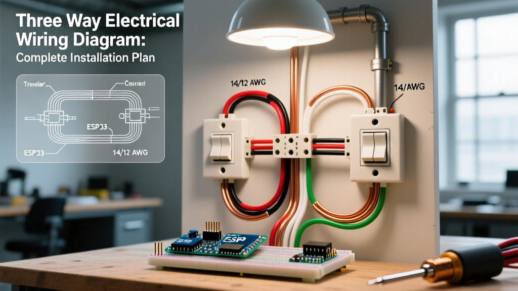
To plan your routing, you must understand the five distinct conductors involved in a standard 3-way circuit. Unlike a single-pole switch that simply breaks the hot line, a 3-way system uses a pair of 'traveler' wires to alternate the path of the current.
- Line (Hot): The ungrounded conductor bringing 120V from the breaker panel to the first switch.
- Load: The ungrounded conductor carrying the switched 120V from the second switch to the light fixture.
- Travelers (x2): The two conductors running between the brass screws of Switch 1 and Switch 2. These alternate carrying the live voltage depending on the toggle positions.
- Neutral (Grounded): The white conductor completing the circuit back to the panel. Crucially, the neutral is never switched and never runs through the traveler terminals.
- Ground (Equipment Grounding): The bare copper or green wire bonding all metal boxes and switch yokes to earth ground for safety.
Routing Configurations: Choosing the Right Diagram
The physical layout of your building dictates which three way electrical wiring diagram topology you must use. Below are the three standard configurations, ranked by preference for new construction.
Configuration 1: Line at Switch 1, Load at Switch 2 (The Gold Standard)
This is the most efficient and code-compliant routing method for new builds.
- Run 14/2 NM-B from the breaker panel to the first switch box (Switch 1).
- Run 14/3 NM-B from Switch 1 to the second switch box (Switch 2). The black and red wires serve as travelers; the white wire serves as the continuous neutral.
- Run 14/2 NM-B from Switch 2 up to the ceiling fixture. The black wire is the switched load; the white wire is the fixture neutral.
Why this works best: It provides a continuous, unbroken neutral path through all switch boxes, perfectly satisfying modern smart-switch requirements without needing extra cables.
Configuration 2: Line and Load at Switch 1 (The Dead-End 3-Way)
Often used in retrofits or when the fixture is physically closer to the first switch.
- Power enters Switch 1 via 14/2. The fixture is also fed directly from Switch 1 via another 14/2.
- A single 14/3 cable runs from Switch 1 to Switch 2. The black wire is the Line, the red and white (re-identified with black tape) are the travelers.
The Planning Catch: Switch 2 becomes a 'dead end' with no neutral wire present. Under current NEC rules, you must either pull an additional 14/2 cable solely to provide a neutral to Switch 2, or use this configuration only where smart switches are explicitly prohibited.
Configuration 3: Power at the Fixture (Legacy Rework)
Common in pre-1990s homes, power drops to the ceiling fixture first, then a 14/3 drops down to Switch 1, and a 14/3 runs to Switch 2. This method is obsolete for new construction due to the complexity of re-identifying neutral wires as hot travelers, which frequently confuses future electricians and violates modern color-coding standards.
NEC 404.2(C): The Neutral Wire Mandate
The most critical planning factor for any 2026 lighting installation is the National Electrical Code requirement regarding neutrals at switch locations. According to the NFPA National Electrical Code, Article 404.2(C), switch boxes controlling lighting loads must contain a neutral conductor.
Code Alert: 'The grounded (neutral) circuit conductor, if present, shall be connected to the neutral terminal of the snap switch.' This was implemented to support electronic timers, occupancy sensors, and smart switches that require a small amount of standby current to operate. If you plan a 3-way circuit without routing a dedicated neutral to both switch boxes, your installation will fail inspection and limit future upgrade paths.
To comply, always default to Configuration 1. If you must use Configuration 2, upgrade your inter-switch cable from 14/3 to 14/4 NM-B, utilizing the extra blue wire as a dedicated traveler so the white wire can remain a permanent, uninterrupted neutral.
Pre-Rough-In Planning Checklist
Before the drywall goes up, verify your installation plan against this actionable checklist to prevent costly tear-outs:
- Box Fill Calculation: Verify that all switch boxes have adequate cubic inch capacity. A standard 3-way box with one 14/2 entering and one 14/3 leaving contains 5 conductors, plus grounds and device yokes. Minimum box size: 20.25 cubic inches (use a 22 or 34 cu. in. deep box for safety).
- Cable Stapling: Plan staple locations every 4.5 feet and within 8 inches of the switch box, per OSHA and NEC 334.30 securing requirements.
- Traveler Identification: Plan to use red electrical tape to mark the white wire in your 14/3 cable if it is being used as a traveler (though proper planning should avoid this entirely).
- Smart Switch Compatibility: If the homeowner plans to use Lutron Caseta or Leviton Decora Smart switches, ensure the load does not exceed the switch's specific LED wattage rating (typically 150W for LEDs, compared to 600W for incandescent).
Commissioning and Multimeter Verification
Once the devices are terminated and power is restored, do not rely solely on flipping the toggle to verify success. Use a True-RMS multimeter, such as the Fluke 117, to verify the integrity of your three way electrical wiring diagram execution.
- Verify Grounding: Measure between the hot line terminal and the metal switch box. You should read exactly 120V (±5V). If you read 0V, your equipment ground is floating—a severe shock hazard.
- Test Traveler Continuity: With the power off, set the multimeter to continuity (beep) mode. Disconnect the travelers at both switches. Probe the red and black wires at Switch 1 and Switch 2 to ensure there are no crossed wires or short circuits inside the walls.
- Check for Phantom Voltage: With the circuit live and the light off, measure the voltage at the fixture socket. A reading of 40V-70V indicates induced phantom voltage on long traveler runs. This is normal but confirms why you must use high-quality LED bulbs with built-in drivers capable of ignoring low-voltage leakage.
For comprehensive termination standards and torque specifications on commercial-grade switches, always refer to the NEMA Wiring Device Termination guidelines to ensure connections do not loosen under thermal expansion over time.
Final Thoughts on Future-Proofing
A meticulously planned 3-way circuit is an investment in the building's electrical infrastructure. By prioritizing continuous neutral routing, utilizing deep junction boxes, and adhering strictly to NEC 404.2(C), you eliminate the most common failure modes associated with multi-location lighting. Whether you are installing standard Leviton toggles or advanced Lutron smart-home ecosystems, the physical wiring topology remains the foundation of a reliable, flicker-free lighting system.