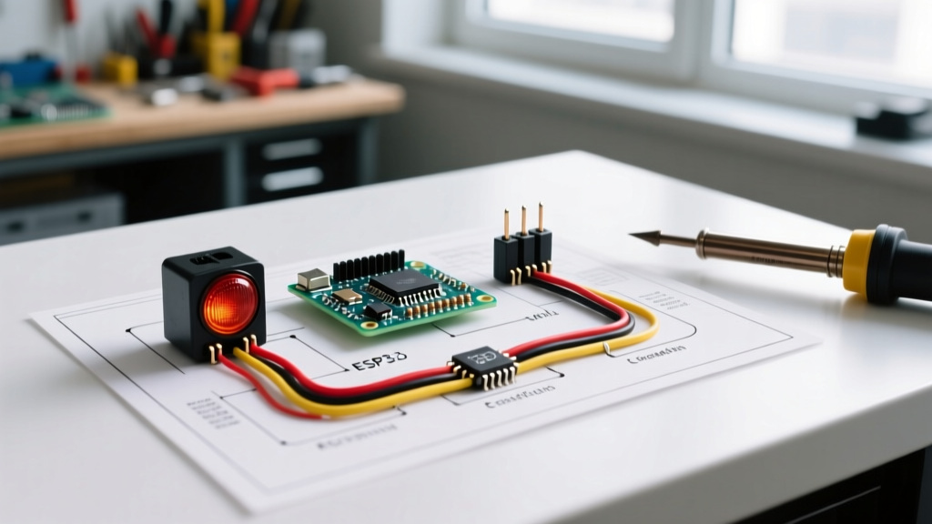

Strategic Planning for Turn Signal Flasher Installations
Upgrading or replacing a vehicle's turn signal relay is a foundational automotive electrical task, yet it frequently results in blown fuses, hyperflashing, or dashboard warning errors when executed without a proper plan. Whether you are restoring a classic muscle car, integrating a custom motorcycle harness, or upgrading a daily driver to modern LED lighting, understanding the exact wiring diagram for turn signal flasher circuits is critical. This installation planning guide provides the technical depth, component specifications, and diagnostic frameworks required to execute a flawless, compliant, and durable electrical integration.
Expert Insight: The most common point of failure in aftermarket lighting installations is not the flasher unit itself, but the reliance on 'T-tap' scotch-lock connectors for splicing. For a reliable connection that withstands engine bay vibrations and moisture, always plan to use adhesive-lined marine-grade heat shrink butt splices.
Thermal vs. Electronic: Selecting the Right Architecture
Before drawing out your wiring schematic, you must determine which flasher technology your vehicle requires. The wiring diagram for turn signal flasher circuits changes fundamentally depending on whether you are using a legacy thermal unit or a modern solid-state electronic unit.
Legacy Thermal Flashers (e.g., Tridon 536, Littelfuse 229)
Thermal flashers rely on a bimetallic strip that heats up and bends to break the circuit, then cools to reconnect it. This creates the classic 'click' sound and the flashing rhythm. Because they depend on electrical resistance and current draw to generate heat, they require a specific minimum load (usually 4.2 Amps total across the circuit). If you install LED bulbs that draw only 0.2 Amps, the bimetallic strip will never heat up, resulting in a solid light or a 'hyperflash' rate exceeding 200 cycles per minute.
Electronic Solid-State Flashers (e.g., Novita EP34, Tridon EL12)
Electronic flashers use an internal integrated circuit (IC) and a timing capacitor to pulse the relay, regardless of the electrical load. They will flash at a consistent, legal rate whether you are running 55-Watt halogen bulbs or 3-Watt LEDs. However, they require a precise wiring configuration, often necessitating a dedicated ground wire that thermal flashers do not need.
Pinout Matrix: 2-Pin vs. 3-Pin Configurations
When reviewing your wiring diagram for turn signal flasher integration, identifying the correct terminal pins is paramount. Use this matrix to map your vehicle's harness to the correct replacement unit.
| Flasher Type | Terminal 1 | Terminal 2 | Terminal 3 | Dashboard Indicator Routing | Best Use Case |
|---|---|---|---|---|---|
| 2-Pin Thermal | B (Battery / 12V+) | L (Load / Lights) | N/A | Wired in parallel with front/rear bulbs | Classic cars, simple halogen setups |
| 2-Pin Electronic | B (Battery / 12V+) | L (Load / Lights) | N/A | Requires parallel routing or LED-compatible dash bulb | LED upgrades on older 2-wire harnesses |
| 3-Pin Electronic | B (Battery / 12V+) | L (Load / Lights) | P (Pilot / Ground) | Dedicated 'P' wire runs directly to dash indicator | Modern vehicles, complex CANbus systems |
Pre-Installation Material and Tool Audit
Do not begin splicing wires until you have verified your materials. A professional-grade installation requires specific components to ensure longevity and safety.
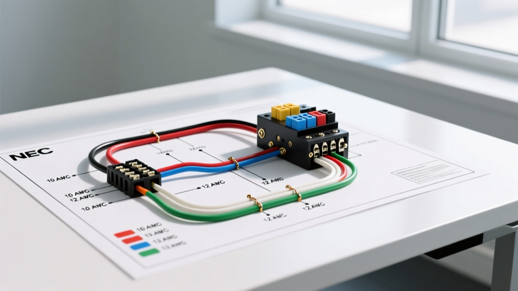
- Wire Gauge: Use 16 AWG stranded copper wire for standard lighting circuits. If you are running multiple high-draw halogen off-road lights through the flasher circuit, upgrade to 14 AWG to prevent voltage drop.
- Connectors: Ancor marine-grade adhesive heat shrink butt connectors (16-14 AWG range).
- Load Resistors (If applicable): If your vehicle uses a CANbus system that cannot be bypassed with an electronic flasher, plan for 6-Ohm 50W aluminum-housed load resistors (approx. $8 to $12 per pair).
- Diagnostic Tool: A digital multimeter (DMM) capable of measuring DC voltage and continuity.
- Replacement Unit: A high-quality electronic flasher like the Novita EP34 (typically $14 to $18) or an OEM-equivalent module.
Step-by-Step Wiring Execution Flow
Follow this precise sequence to execute the wiring diagram for turn signal flasher installation without damaging the vehicle's Body Control Module (BCM) or fuse panel.
Step 1: Isolate and Probe the Factory Harness
- Disconnect the negative battery terminal using a 10mm wrench to prevent accidental short circuits.
- Locate the factory flasher relay. It is typically found under the dashboard near the steering column, inside the fuse panel, or in the engine bay relay box.
- Reconnect the battery temporarily, turn the ignition to the 'ON' position (engine off), and activate the hazard switch.
- Use your DMM set to DC Voltage. Probe the harness connector pins. The pin showing a steady 12.2V to 12.6V is your 'B' (Battery) feed. The pin that pulses voltage when the turn signal stalk is engaged is your 'L' (Load) feed.
Step 2: Execute the Splices
- Disconnect the battery again. Strip exactly 5/16 inch of insulation from the factory wires and your new pigtail wires.
- Insert the wires into the adhesive-lined heat shrink butt connectors and crimp using a ratcheting crimping tool. A proper crimp should require approximately 30 lbs of pull-force to separate.
- Apply heat evenly until the adhesive oozes from the ends of the shrink tube, ensuring a watertight seal.
Step 3: Integrate the Ground (For 3-Pin Systems)
If your wiring diagram for turn signal flasher setups requires a 3-pin electronic relay, you must establish a dedicated ground for the 'P' (Pilot) terminal. Do not simply wrap the wire around a bolt. Use a 1/4-inch ring terminal, sand the chassis mounting point down to bare metal, apply dielectric grease over the terminal after bolting it down, and secure it with a star washer to bite through any residual paint or rust.
Troubleshooting Edge Cases and Failure Modes
Even with a perfect wiring diagram, real-world variables can cause anomalies. Use this diagnostic framework to resolve post-installation issues.
Symptom: Hyperflashing (Rapid Blinking)
Cause: The flasher unit is detecting a low-load condition, usually because LED bulbs were installed without an electronic flasher or load resistors. Alternatively, a single halogen bulb has a blown filament, dropping the total circuit resistance. Resolution: Swap the thermal flasher for a solid-state electronic unit (like the Novita EP34). If the vehicle uses a hard-coded BCM, install 6-Ohm 50W resistors in parallel with the LED bulbs to simulate the 2.1 Amp draw of a halogen bulb.
Symptom: Solid Illumination (No Flashing)
Cause: The flasher unit is not receiving enough current to trigger the internal timing circuit, or the 'B' and 'L' pins are reversed on a polarity-sensitive electronic flasher. Resolution: Swap the B and L wire connections at the relay plug. Verify that the inline fuse (usually 10A or 15A) has not blown due to a short in the rear tail light housing.
Symptom: Dashboard Indicator Stays On Solid
Cause: In a 2-pin electronic flasher setup, the dashboard indicator bulb is feeding back voltage through the filament, confusing the flasher's internal logic. Resolution: Replace the incandescent dashboard indicator bulb with an LED equivalent, or install a dedicated diode in the dash indicator wire to enforce one-way current flow.
Regulatory Compliance and Safety Standards
When modifying exterior lighting circuits, your installation must comply with federal safety regulations. According to the Federal Motor Vehicle Safety Standards (FMVSS 108), turn signal lamps must flash at a rate of not less than 60 and not more than 120 flashes per minute. Furthermore, the 'on' time must not be less than the 'off' time. Using an adjustable electronic flasher allows you to dial in the exact cycles-per-minute (CPM) rate to ensure your vehicle remains street-legal and passes state safety inspections. For deeper technical specifications on automotive relay tolerances and lifecycle testing, refer to the engineering guidelines provided by major component manufacturers like Littelfuse Automotive Relays.
Final Inspection Checklist
Before reassembling the dashboard or engine bay covers, complete this final audit:
- Verify left and right turn signals flash independently without cross-feeding.
- Confirm the hazard switch overrides the turn signal stalk and flashes all four corners simultaneously.
- Check that the brake light circuit is completely isolated from the turn signal circuit (unless using a dedicated tail-light-to-turn-signal converter module on European vehicles).
- Perform a voltage drop test across the new flasher unit while the lights are active; a drop greater than 0.5V indicates high resistance in your crimps or an undersized wire gauge.
By treating the wiring diagram for turn signal flasher integration as a comprehensive system rather than a simple plug-and-play swap, you ensure reliable operation, legal compliance, and a professional-grade finish that withstands the harsh automotive environment.