
The Evolution of Dryer Receptacles: Why the NEC Mandated 4-Prong
Understanding an electric dryer wiring diagram requires a brief look into electrical code history. Prior to 1996, the National Electrical Code (NEC) allowed 3-prong NEMA 10-30R receptacles for electric dryers. In this older configuration, the equipment ground and the neutral wire were bonded together at the appliance. While this saved copper, it created a severe shock hazard: if the neutral wire broke or developed high resistance, the 120V return current would backfeed through the grounding path, energizing the metal chassis of the dryer.
To eliminate this risk, the National Electrical Code (NEC) updated Article 250.140 to mandate separate neutral and ground paths for all new installations. Today, the 4-prong NEMA 14-30R is the absolute standard for new construction. However, because millions of older homes still feature 3-prong outlets, DIYers and electricians frequently need to interpret wiring diagrams to safely convert dryer cords or upgrade receptacles.
Anatomy of an Electric Dryer Wiring Diagram
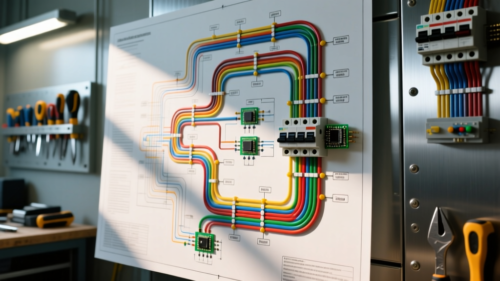
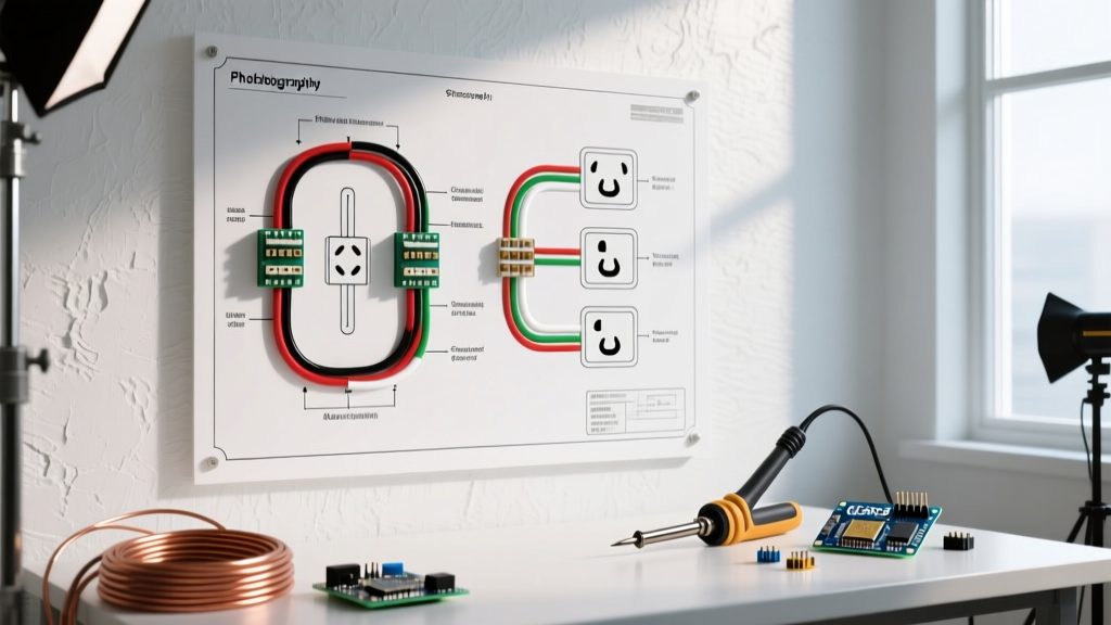
When you pull the terminal block cover off the back of a modern electric dryer (such as a standard Whirlpool WED4815EW or LG DLE7000W), you will see a terminal block with three or four connection points. A proper electric dryer wiring diagram maps the incoming 240V/120V split-phase power to these specific terminals:
- L1 (Line 1): Carries 120V from one leg of the panel.
- L2 (Line 2): Carries 120V from the opposite leg (totaling 240V across L1 and L2).
- N (Neutral): The grounded conductor that provides the 120V return path for the motor, timer, and control board.
- G (Ground): The equipment grounding conductor, bonded directly to the dryer's metal frame.
The 240V / 120V Split Load
The most misunderstood aspect of dryer wiring is the split-load requirement. The heavy heating element requires the full 240V (L1 to L2) to generate adequate BTUs. However, the drum motor, interior light, and digital control boards operate strictly on 120V (L1 to Neutral or L2 to Neutral). If your wiring diagram is misinterpreted and the neutral is disconnected, the control board will starve, and the dryer will fail to start, even if the 240V heating circuit is intact.
3-Prong vs. 4-Prong Configuration Matrix
Use the following matrix to identify your current setup and the required cable type before beginning any wiring work.
| Feature | 3-Prong Setup (Legacy) | 4-Prong Setup (Modern NEC) |
|---|---|---|
| Receptacle Type | NEMA 10-30R | NEMA 14-30R |
| Plug Type | NEMA 10-30P | NEMA 14-30P |
| Cable Required | 10/3 NM-B (No separate ground) | 10/4 NM-B (Dedicated ground) |
| Neutral/Ground Bond | Bonded AT the appliance | Bonded ONLY at the main panel |
| Safety Level | Shock risk if neutral fails | High (Independent ground path) |
Step-by-Step: Wiring a 4-Prong NEMA 14-30R Receptacle
If you are upgrading an older laundry room to meet current safety standards, you must pull a new 10/4 NM-B (Romex) cable from your main service panel. According to the Electrical Safety Foundation International (ESFI), working inside a main panel requires turning off the main breaker and verifying zero voltage with a CAT III or CAT IV multimeter.
- Breaker Installation: Install a 30-amp double-pole breaker (e.g., Square D HOM230 or Siemens Q230) into the panel. Ensure it snaps firmly onto both hot bus bars.
- Panel Connections: Connect the black and red (or white with black tape) wires to the breaker terminals. Connect the bare copper wire to the grounding bar. Connect the white neutral wire to the isolated neutral bar. Torque all terminal screws to the manufacturer's specification (typically 35-45 in-lbs for 10 AWG wire).
- Receptacle Wiring: At the NEMA 14-30R outlet, connect the two hot wires to the brass 'X' and 'Y' terminals. Connect the white neutral to the silver 'W' terminal. Connect the bare ground to the green 'G' terminal.
- Final Check: Before plugging in the dryer, test the receptacle with a multimeter. You should read 240V across X and Y, and 120V from X to W, and Y to W.
The Critical Conversion: 3-Prong Cord to 4-Prong Cord
The most dangerous scenario in appliance wiring occurs when a homeowner buys a new dryer with a 4-prong cord and plugs it into an older 3-prong outlet using an adapter, or installs a 4-prong cord but fails to remove the internal bonding strap. Never leave the neutral-to-ground bonding strap in place when using a 4-prong cord.
WARNING: If the bonding strap is left connected on a 4-prong setup, normal 120V neutral return current will flow through the equipment ground wire. This energizes the dryer chassis and can cause a lethal shock if the ground wire fails or is compromised.
How to properly convert the dryer terminal block:
- Locate the green grounding screw on the dryer's metal back panel.
- Find the copper bonding strap (or a green bonding wire) that connects the center neutral terminal to the metal chassis.
- Remove this strap entirely. Fold it back and secure it with electrical tape so it cannot accidentally touch a terminal.
- Connect the 4-prong cord's center white wire to the center neutral terminal.
- Connect the 4-prong cord's green ground wire to the green grounding screw on the chassis.
- Connect the two outer hot wires to the L1 and L2 terminals. (Polarity between L1 and L2 does not matter for standard dryers).
- Torque the terminal block screws to 12-15 in-lbs to prevent arcing and thermal buildup.
Wire Gauge, Voltage Drop, and Breaker Sizing
Electric dryers are continuous, high-draw appliances. NEC Article 210.19 requires branch circuits to be sized at 125% of the continuous load. Since most residential dryers draw between 22 and 26 amps at 240V, a 30-amp circuit using 10 AWG copper wire is the legal minimum and industry standard.
However, wire gauge must be adjusted for distance to prevent voltage drop. If your laundry room is located more than 50 feet from the main electrical panel, the resistance in 10 AWG wire will cause a voltage drop exceeding the recommended 3%. This results in the heating element taking significantly longer to dry clothes, wasting energy and stressing the motor.
- Under 50 feet: 10/4 NM-B Copper (30A Breaker)
- 50 to 100 feet: 8/4 NM-B Copper (30A Breaker)
- Over 100 feet: 6/4 NM-B Copper (30A Breaker)
Note: You cannot increase the breaker size to 40A for a standard dryer receptacle. The NEMA 14-30R receptacle and the dryer's internal wiring are strictly rated for a maximum of 30 amps. Upgrading the wire gauge for distance is done solely to maintain voltage, not to increase amperage capacity.
Troubleshooting Common Wiring Failure Modes
Even with a perfect electric dryer wiring diagram, installation errors happen. Here is how to diagnose the three most common post-wiring failure modes:
1. Dryer Tumbles but Produces No Heat
Cause: One of the 120V legs (L1 or L2) is dead. The drum motor only requires 120V (L1 to Neutral), so it will run. However, the heating element requires the full 240V (L1 to L2). If one breaker pole failed to seat, or a hot wire is loose at the receptacle, the heater will not energize.
Fix: Test voltage across the X and Y terminals at the receptacle. If you read 120V instead of 240V, check the double-pole breaker and the hot terminal connections.
2. Breaker Trips Immediately Upon Starting
Cause: A neutral-to-ground short. This almost always happens during a 3-prong to 4-prong cord conversion when the installer forgets to remove the internal bonding strap. When the dryer calls for 120V power, the return current splits between the neutral wire and the ground wire, creating an imbalance that trips the breaker (if on an AFCI/GFCI) or causes a direct short if the ground and neutral touch downstream.
Fix: Unplug the dryer, remove the terminal cover, and verify the bonding strap has been completely removed and isolated.
3. Digital Control Board Fries or Behaves Erratically
Cause: Overvoltage due to a lost neutral on a multi-wire branch circuit, or wiring the 240V hot legs into the neutral terminal. This sends 240V directly into 120V-sensitive logic boards, instantly destroying the triacs and capacitors.
Fix: Always verify the receptacle wiring with a multimeter before plugging in the appliance. Ensure the white neutral wire is exclusively connected to the silver 'W' terminal on the NEMA 14-30R.