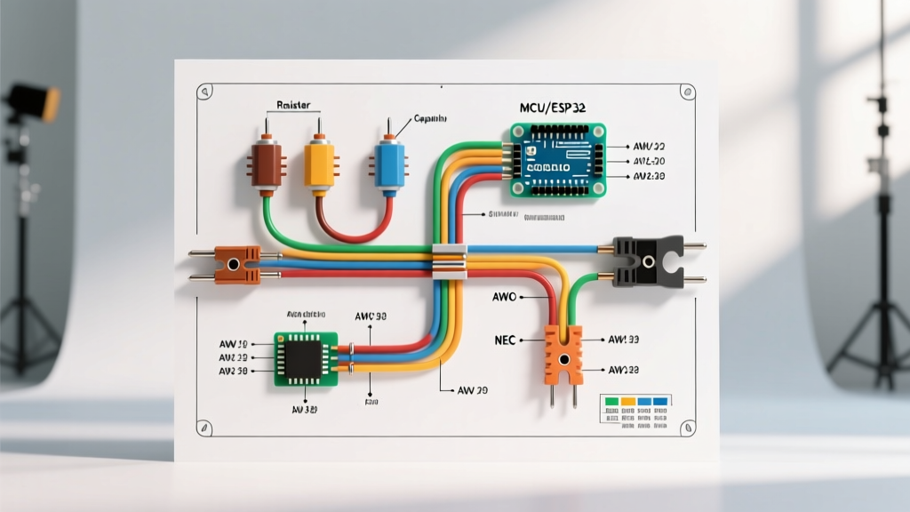

The Bridge Between Schematics and Physical Reality
A schematic is only as useful as your ability to translate its abstract lines into physical copper, insulation, and terminals. When working with complex panels, HVAC systems, or custom microcontroller enclosures, understanding wiring diagram symbols electrical standards is just the first step. The true expertise lies in mapping those 2D symbols to real-world wire gauges, ampacity limits, and strict color code compliance.
Amateurs see a simple line connecting a breaker to a receptacle. Professionals see a 12 AWG THHN copper conductor, limited to a 20A overcurrent protective device (OCPD), routed with a specific neutral and ground identification. This guide bridges the gap between abstract electrical symbols and the physical wire gauge and color code references required for safe, code-compliant installations in 2026.
Core Wiring Diagram Symbols Electrical Engineers Use Daily
Before selecting wire gauges, you must accurately interpret the schematic. Misreading a junction as a crossover can lead to catastrophic short circuits. Below is a reference matrix of the most critical symbols you will encounter in residential, commercial, and industrial diagrams.
| Symbol Name | Visual Representation | Physical Meaning & Action Required |
|---|---|---|
| Connected Junction | Solid Dot at Intersection | Wires are physically spliced. Requires a wire nut, Wago connector, or terminal block. Ensure gauge compatibility. |
| Non-Connected Crossover | Lines Crossing (No Dot) or 'Hop' | Wires cross but do not connect. Maintain physical separation in the panel to prevent inductive interference. |
| Chassis Ground | Three Decreasing Horizontal Lines | Connection to the metal enclosure. Requires a green grounding screw and star washer to bite through paint. |
| Earth Ground | Line with Three Splayed Prongs | Connection to a grounding electrode (rod). Must use bare copper or green-insulated wire per NEC standards. |
| Shielded Cable | Line Enclosed in a Dashed Circle | Indicates coaxial or shielded twisted pair. The shield must be grounded at one end only to prevent ground loops. |
Translating Symbols to Wire Gauge (AWG) Specifications
Schematics rarely draw wires to scale. A line representing a 14 AWG lighting circuit looks identical to a line representing a 4/0 AWG main service feeder. You must rely on the text annotations next to the wiring diagram symbols electrical layouts to determine the American Wire Gauge (AWG).
The Ampacity Trap: NEC Table 310.16 vs. 240.4(D)
One of the most dangerous edge cases in electrical wiring is the 'ampacity trap.' Many DIYers look at a diagram, see a 12 AWG wire, and assume they can protect it with a 30A breaker because the 90°C column in NEC Table 310.16 lists THHN 12 AWG at 30A.
Expert Warning: NEC 240.4(D) specifically restricts small conductors. 12 AWG copper is strictly limited to 20A overcurrent protection, and 14 AWG is limited to 15A, regardless of the insulation's high thermal rating. Always size your breaker based on the 60°C or 75°C termination limits and NEC small conductor rules, not the wire's maximum thermal threshold.
Standard AWG Quick-Reference for Branch Circuits
- 14 AWG: 15A maximum. Used for general lighting and low-draw receptacles. (1.628 mm diameter)
- 12 AWG: 20A maximum. Used for kitchen, bathroom, and outdoor receptacles. (2.053 mm diameter)
- 10 AWG: 30A maximum. Used for electric water heaters, dryers (120V components), and heavy power tools. (2.588 mm diameter)
- 8 AWG: 40A maximum. Used for EV chargers (Level 2, lower tier) and large HVAC compressors. (3.264 mm diameter)
- 6 AWG: 55A to 65A maximum (depending on insulation). Standard for 50A RV receptacles and subpanels. (4.115 mm diameter)
For precise metric conversions and resistance calculations over long distances, the Engineering Toolbox AWG reference remains the industry standard for calculating voltage drop, which becomes critical for runs exceeding 100 feet.
Color Code Standards: What the Lines on the Diagram Actually Mean
While wiring diagram symbols electrical drafts use varied line styles (dashed, solid, dotted) to denote different circuits, the physical installation must adhere to strict color codes. Mixing up AC and DC color codes is a primary cause of equipment failure in hybrid systems like solar inverters or HVAC control boards.
AC Power Wiring Color Codes (NEC Standards)
In the United States, the National Electrical Code (NEC) mandates specific colors for alternating current systems to ensure safety during maintenance and troubleshooting.
- Black, Red, Blue: Ungrounded conductors (Hot/Phase). In a 3-phase 208V system, these represent Phase A, B, and C respectively.
- White or Gray: Grounded conductor (Neutral). Edge Case: If a white wire is used as a hot leg in a switch loop or 240V appliance, it must be re-identified with black electrical tape or paint at both ends.
- Green, Green/Yellow Stripe, or Bare Copper: Equipment grounding conductor (EGC). Never use these colors for current-carrying conductors.
DC and Low-Voltage Electronics Color Codes
When your schematic transitions from the mains panel to a 24V DC control circuit (common in industrial PLCs or modern smart home panels), the color rules change entirely.
- Red: Positive voltage (+VDC). Typically 12V, 24V, or 48V depending on the system.
- Black: Negative or Ground (-VDC). Warning: In AC systems, black is hot. In DC systems, black is negative/return. Always verify with a multimeter before assuming.
- Yellow/White: Often used for signal wires, data lines (like RS-485 or Modbus), or switched DC outputs.
Advanced Schematic Notations: Shielding and Twisted Pairs
Modern electrical diagrams frequently include low-voltage communication lines running parallel to high-voltage AC lines. Understanding the specific symbols for these cables is vital to prevent electromagnetic interference (EMI).
Twisted Pair and Shielding Symbols
If you see a wire line enclosed in a dashed or solid boundary, this indicates a shielded cable. In environments with heavy variable frequency drives (VFDs) or large contactors, unshielded communication wires will pick up inductive noise, causing microcontrollers to reset or data packets to drop.
Installation Rule: When terminating a shielded twisted pair (STP) cable indicated on your diagram, the drain wire must be terminated to the chassis ground at one end only. Grounding both ends creates a ground loop, turning your shield into an antenna that amplifies the very noise it was meant to block.
Troubleshooting Edge Cases: When the Diagram Lies
Even with a perfect grasp of wiring diagram symbols electrical conventions, real-world installations often deviate from the schematic. Here are two critical edge cases to watch for during commissioning and repair:
- Phantom Voltages on Disconnected Wires: When using a high-impedance digital multimeter (DMM), you may read 40V to 80V on a wire that the diagram shows as completely disconnected. This is capacitive coupling from adjacent live wires in the same conduit. Always use a low-impedance (LoZ) meter or a solenoid voltage tester (Wiggie) to confirm a true dead circuit.
- Shared Neutrals (Multi-Wire Branch Circuits): A diagram might show two separate 120V circuits on different breakers. If they share a single 12 AWG neutral wire (a Multi-Wire Branch Circuit or MWBC), the breakers must be on opposite phases (240V between them) and tied together with a handle tie. If they are on the same phase, the neutral wire will carry the sum of both currents, overloading the 12 AWG wire and creating a severe fire hazard without tripping the breakers.
Frequently Asked Questions
What does a circle with a line through it mean on an electrical diagram?
A circle with a diagonal line or a specific letter inside usually represents a specific type of disconnect, relay coil, or motor starter. If it is a simple circle with a line crossing it entirely, it often denotes a terminal block connection point where field wiring meets factory wiring.
How do I identify wire gauge if the diagram doesn't specify AWG?
If the schematic lacks AWG annotations, look for the overcurrent protection device (breaker or fuse) rating associated with that circuit. Use NEC Table 310.16 and 240.4(D) to back-calculate the minimum required copper wire gauge. For example, a 40A breaker dictates a minimum of 8 AWG copper wire.
Are IEC color codes different from NEC color codes?
Yes, drastically. The International Electrotechnical Commission (IEC) uses Brown, Black, and Gray for AC phases, and Blue for Neutral. The earth ground is Green/Yellow. If you are importing equipment from Europe or working on international marine vessels, you must reference IEC 60446 standards rather than US NEC standards to avoid lethal miswiring.
Mastering the translation from abstract wiring diagram symbols electrical layouts to physical wire gauges and color codes is what separates a theoretical understanding from professional, safe execution. Always verify local codes and measure twice before energizing any new circuit.