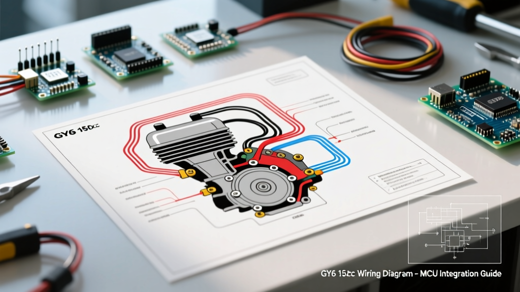

Understanding the GY6 150cc Electrical Architecture
The GY6 150cc engine (commonly stamped with the 157QMJ designation) is the backbone of the global scooter, go-kart, and buggy market. Brands like TaoTao, Roketa, Ice Bear, and Kymco rely on this robust 4-stroke powerplant. However, the electrical harnesses on these vehicles are notorious for connector corrosion, chafed insulation, and aftermarket splicing errors. When your scooter refuses to start or your battery keeps dying, guessing is not an option. You need to systematically trace the circuit using a proper wiring diagram for GY6 150cc applications.
Unlike modern fuel-injected motorcycles, the GY6 utilizes a relatively simple magneto-stator hybrid system paired with an AC-CDI (Capacitor Discharge Ignition) and a shunt-style rectifier/regulator. By understanding how to map the physical wires to the schematic, you can isolate faults in minutes rather than hours.
Decoding Standard GY6 Wire Color Codes
Chinese manufacturing standards for the GY6 platform generally adhere to a specific color-coding scheme. While aftermarket harnesses sometimes deviate, the following table represents the factory-standard wire colors you will see on your wiring diagram for GY6 150cc engines.
| Wire Color | Function | System / Component |
|---|---|---|
| Black / White | Kill Switch / Ignition Ground | Grounds CDI to stop engine |
| Black / Red | Ignition Source (AC) | Stator Ignition Winding to CDI |
| Blue / White | Pickup / Trigger Coil Signal | Stator Pickup to CDI |
| White | AC Charging Output | Stator to Rectifier/Regulator |
| Yellow | AC Headlight / Charging Output | Stator to Headlight Switch & Rectifier |
| Pink / Purple | High Voltage Trigger | CDI Output to Ignition Coil Primary |
| Green | Chassis Ground | Common Ground for all DC circuits |
| Red | Battery Positive (12V DC) | Rectifier DC out to Battery / Fuse |
Scenario A: Cranks But Has No Spark
The most common reason DIY mechanics pull up a GY6 wiring diagram is a no-spark condition. The engine cranks via the starter motor, but the ignition coil never fires. To troubleshoot this, we trace the ignition circuit backward from the spark plug cap to the stator.
Step 1: Test the Ignition Coil
Disconnect the spark plug cap and remove the ignition coil from the engine. Set your digital multimeter to the 200Ω (Ohms) range. Measure the primary winding by placing one probe on the coil's primary terminal (usually a female spade connector receiving the Pink/Purple wire) and the other on the coil's mounting tab (ground). A healthy primary winding reads between 0.1 and 0.5 ohms. Next, switch your multimeter to the 20kΩ range and measure the secondary winding by probing the primary terminal and the inside of the spark plug boot. You should see 4,000 to 15,000 ohms. If either reading is infinite (open) or zero (shorted), replace the coil.
Step 2: Verify the Pickup Coil and Stator Windings
If the ignition coil tests fine, the fault lies upstream. Locate the stator plug (usually a 4-pin or 6-pin white plastic connector near the CVT transmission cover). Disconnect it and set your multimeter to the 2kΩ range.
- Pickup Coil (Blue/White to Green): Should read between 100 and 190 ohms. This sensor tells the CDI exactly when the piston is approaching Top Dead Center (TDC).
- Ignition Source Winding (Black/Red to Green): Should read between 300 and 450 ohms. This dedicated winding generates the raw AC voltage that the CDI stores and discharges.
For comprehensive stator and rectifier testing methodologies that apply to small engines and motorcycles, refer to the diagnostic standards outlined by RevZilla's Common Tread technical guide.
Step 3: The Kill Switch Trap
Pro-Tip: The GY6 ignition system is "normally on." It only stops firing when the Black/White wire is grounded. If your run switch, brake lever switches, or side-stand relay are faulty and permanently grounding the Black/White wire, the CDI will never fire. Unplug the main harness from the CDI; if you have spark with the harness disconnected but the Black/Red and Blue/White wires manually jumped, your fault is a shorted kill switch circuit in the chassis harness.
Scenario B: Battery Not Charging (Shunt Rectifier Diagnostics)
A dead battery on a GY6 150cc is rarely a bad battery; it is usually a failed rectifier or a melted stator plug. The GY6 uses a shunt-type rectifier/regulator. Unlike automotive alternators that vary their magnetic field to control output, the GY6 stator runs at full capacity constantly. The rectifier converts the AC to DC and "shunts" (shorts to ground) any excess AC voltage to keep the DC output at a safe ~14.2V.
Testing Stator AC Output
Start the scooter and let it idle. Set your multimeter to AC Volts (V~). Probe the White and Yellow wires directly at the stator plug (engine side). At idle (approx. 1,500 RPM), you should see 15V to 25V AC. Rev the engine to 3,000 RPM; the voltage should climb to 35V to 45V AC. If you read 0V AC on either wire, your stator is burnt out or the flywheel magnets have demagnetized (a common issue if the flywheel was subjected to extreme heat or physical impact).
Testing Rectifier DC Output
Switch your multimeter to DC Volts (V⎓). With the engine running at 3,000 RPM and the headlight turned ON (to apply a load), probe the Red wire (DC out) and the Green wire (Ground). A healthy system will read between 13.5V and 14.5V DC.
- Reading above 15V DC: The rectifier's shunt circuit has failed open. It is no longer grounding excess voltage. This will boil your battery acid and blow your headlight bulbs.
- Reading below 12.5V DC: The rectifier diodes are likely fried, or the White/Yellow stator wires have high resistance due to a melted connector. As noted in Fluke's automotive electrical testing guidelines, voltage drop testing across connectors is critical when dealing with high-current charging circuits.
The Infamous GY6 Headlight DC Mod
Out of the factory, the GY6 150cc headlight is wired directly to the Yellow stator wire. This means the headlight runs on raw, unregulated AC power. The light dims at idle and brightens at high RPM, frequently blowing bulbs due to voltage spikes. Using your wiring diagram for GY6 150cc layouts, you can perform the highly recommended "DC Headlight Mod."
- Cut the Yellow wire coming from the stator before it reaches the handlebar headlight switch.
- Route this stator Yellow wire exclusively to the Rectifier's AC input (it may already be spliced there, just ensure it doesn't continue to the handlebars).
- Run a new 14-gauge wire from a key-switched 12V DC source (like the brake light fuse tap) to the handlebar headlight switch.
This forces the headlight to run off the battery's regulated 12V DC, providing rock-solid illumination at idle and vastly extending bulb life.
2026 Replacement Parts & Tooling Guide
Supply chains for 157QMJ components have stabilized significantly by 2026, making OEM and performance replacement parts highly affordable. Below is a realistic pricing and tooling matrix for your GY6 electrical rebuild.
| Component / Tool | Specification / Notes | Estimated 2026 Cost |
|---|---|---|
| OEM Stator Assembly | 8-pole magneto, 4-pin plug | $28.00 - $42.00 |
| Performance AC-CDI | Unrestricted, 6-pin (adapts to 4-pin) | $16.00 - $25.00 |
| MOSFET Rectifier Upgrade | Replaces stock shunt, runs cooler | $35.00 - $55.00 |
| Digital Multimeter | True RMS, Auto-ranging (e.g., Fluke 115) | $160.00 - $210.00 |
| Solder Seal Wire Connectors | Heat shrink with adhesive lining | $12.00 (Pack of 50) |
Final Troubleshooting Best Practices
When diagnosing electrical gremlins on Chinese scooters and buggies, never trust the visual condition of a wire. A wire that looks perfectly intact on the outside can be corroded to dust inside the insulation due to capillary action from a wet connector. Always use a multimeter to perform continuity and voltage drop tests. By methodically following the wiring diagram for GY6 150cc circuits, verifying resistance at the stator, and validating the rectifier's shunt behavior, you can conquer any electrical fault this engine throws your way. For foundational multimeter techniques, the Family Handyman multimeter guide is an excellent prerequisite resource for beginners tackling their first stator diagnosis.