
Decoding the 1997 GMT400 Electrical Architecture
Before diving into the specific wiring diagram for 1997 Chevy Silverado models, we must address a critical nomenclature nuance that confuses many DIYers and parts counters. In 1997, General Motors was still producing the GMT400 platform. Officially, these trucks were badged as the Chevrolet C1500 (2WD) or K1500 (4WD). The 'Silverado' name was technically a trim level (alongside Cheyenne and WT) until 1999, when GM launched the GMT800 platform and made Silverado the standalone model name. However, because the consumer market universally refers to the 1994-1998 GMT400 OBS (Old Body Style) trucks as Silverados, finding the correct OEM documentation requires understanding this crossover.
The 1997 model year is particularly unique in the GMT400 lineage. It represents a transitional period where GM integrated OBD-II compliance (mandated for all 1996+ vehicles) while retaining much of the robust, modular electrical architecture from the early 1990s. Whether you are troubleshooting a parasitic draw, installing an aftermarket stereo, or diagnosing a no-start condition on a Vortec 5.7L (L31), understanding the core circuits is essential.
Headlight and Daytime Running Light (DRL) Circuit
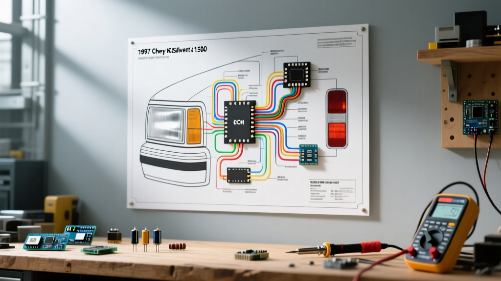
The 1997 GMT400 lighting circuit is notorious for voltage drop issues, primarily due to the headlight switch carrying the full amperage load for the headlights without the use of relays from the factory. When analyzing the wiring diagram for 1997 Chevy Silverado trucks, you will notice the headlight switch receives battery voltage via a 12 AWG Red wire. The output splits into a 12 AWG Tan wire (parking lights) and a 12 AWG Brown wire (headlights).
Understanding the DRL Module
Unlike modern trucks that use the Body Control Module (BCM) for Daytime Running Lights, the 1997 C/K 1500 utilizes a standalone DRL module, typically mounted on the left inner fender near the master cylinder. The DRL module intercepts the high-beam circuit. When the parking brake is released and the transmission is in gear, the DRL module sends a reduced-voltage PWM (Pulse Width Modulated) signal to the high-beam filaments, causing them to glow dimly.
- Left High Beam Feed: Yellow (18 AWG from DRL, steps up to 12 AWG at the bulkhead)
- Right High Beam Feed: Dark Green
- Left Low Beam Feed: Tan
- Right Low Beam Feed: Light Green
Expert Tip: If your high beams flicker or only work when you pull the 'Flash-to-Pass' lever on the column, the multifunction switch (turn signal stalk) internal contacts are likely pitted. Standard Motor Products (SMP) part number S-559 is the recommended heavy-duty pigtail replacement for the headlight switch harness, which frequently melts due to the 15-amp continuous draw.
The Infamous Vortec Fuel Pump Relay 'Gray Wire' Failure
If you are using a wiring diagram for 1997 Chevy Silverado trucks to diagnose a crank-no-start condition, you must inspect the fuel pump relay circuit. The 1997 Vortec 5.0L (L30) and 5.7L (L31) engines rely on a specific fuel pump prime sequence. When the key is turned to the 'ON' position, the Vehicle Control Module (VCM/PCM) grounds the fuel pump relay for exactly two seconds to prime the spider injection system.
Critical Failure Mode: The 12 AWG Gray wire that carries the switched 12V from the fuel pump relay to the fuel pump sender assembly is a known weak point. The spade terminal inside the relay block often loosens over time, causing high resistance. This leads to the terminal arcing, melting the plastic relay housing, and eventually causing a complete loss of fuel pressure. Always inspect the Gray wire terminal for heat discoloration when diagnosing Vortec fuel starvation.
To fix this, do not simply swap the relay. Use a ratcheting crimp tool to replace the female spade terminal on the Gray wire, or replace the entire pigtail using an SMP S-816 harness connector to ensure a tight, low-resistance connection.
OBD-II Data Link Connector (DLC) Pinout
The 1997 model year fully embraces the 16-pin J1962 OBD-II Data Link Connector, located under the driver's side dash near the hood release. Unlike the 1996 models which sometimes featured a hybrid ALDL/OBD-II setup, the 1997 GMT400 strictly uses GM's Class 2 Serial Data protocol for powertrain diagnostics. Below is the exact pinout configuration for the 1997 C/K 1500 DLC.
| Pin | Wire Color | Function / Signal |
|---|---|---|
| 2 | Purple | Class 2 Serial Data (PCM Communication) |
| 4 | Black | Chassis Ground |
| 5 | Black/White | Signal Ground (PCM Reference) |
| 9 | Tan | Serial Data (Optional / ABS Module) |
| 12 | Purple/White | Class 2 Serial Data (Secondary / BCM if equipped) |
| 16 | Orange | Battery Positive (Constant 12V) |
For deeper diagnostic protocols and standard J1962 compliance metrics, refer to the OBD-Codes J1962 Pinout Guide. If your scan tool will not power on, check the Orange wire (Pin 16) for constant 12V and verify the Black wire (Pin 4) has continuity to the chassis. A broken ground at Pin 4 is the most common reason cheap Bluetooth OBD-II dongles fail to pair with the 1997 PCM.
GMT400 Grounding Architecture: The Root of All Evil
No guide to the wiring diagram for 1997 Chevy Silverado trucks is complete without addressing the grounding system. GM utilized a 'daisy-chain' grounding strategy in the GMT400 era, where multiple sensors and modules share a single ground point bolted to the chassis or engine block. When these points corrode, they create 'floating grounds,' leading to bizarre electrical gremlins like gauges sweeping to maximum, fuel pumps running backward, or the ABS light illuminating randomly.
Critical Ground Locations to Clean
- G100 (Left Front Fender): Grounds the left headlight, parking light, and the left side of the radiator support. Located behind the left headlight assembly bolted to the fender.
- G102 (Engine Block Rear): The main PCM and engine sensor ground. Located on the passenger side rear of the cylinder head. Must be cleaned with a wire wheel down to bare aluminum.
- G200 (Right Rear Quarter Panel): Grounds the right taillight, fuel pump sender, and ABS module. Located inside the cab, behind the right-side kick panel or under the rear seat depending on cab configuration.
- G300 (Rear Crossmember): Grounds the trailer harness and rear bumper lights. Highly prone to corrosion from road salt and water intrusion.
For community-tested grounding relocation strategies and heavy-duty upgrade paths, the GM Truck Club GMT400 Grounding Thread is an invaluable resource for OBS owners.
Rear Lighting and 7-Way Trailer Harness Integration
The 1997 C/K 1500 tailgate wiring harness is a frequent failure point due to the constant flexing of the harness every time the tailgate is opened and closed. The wires pass through a rubber boot near the left tailgate hinge. Over time, the 16 AWG copper strands fracture internally, causing intermittent brake lights or turn signals.
OEM Tailgate Wire Colors
- Brown (16 AWG): Tail/Marker/Running Lights
- Dark Green (16 AWG): Right Stop/Turn Signal
- Yellow (16 AWG): Left Stop/Turn Signal
- Light Blue (16 AWG): Backup Lamps
- Black (16 AWG): Ground
If your truck is equipped with the factory RPO Z82 trailer towing package, it features a 7-way RV blade connector at the rear bumper. The factory harness uses a separate relay block under the hood (near the master cylinder) to isolate the trailer lighting draw from the truck's internal lighting circuit. If the trailer running lights do not work but the truck's tail lights do, check the 30-amp Maxi fuse labeled 'TRLR PRK' in the under-hood fuse block, and verify the brown wire output from the trailer lighting relay.
Frequently Asked Questions (FAQ)
Where is the flasher relay located on a 1997 Chevy Silverado?
Unlike older vehicles that use a simple thermal flasher can plugged into the fuse block, the 1997 GMT400 uses an electronic combination flasher module. It is located under the driver's side dash, plugged directly into the convenience center (a multi-port plug-in block near the steering column). It is a square, black or gray plastic module. If your turn signals stay solid or flash rapidly on both sides, replace it with an electronic LED-compatible flasher if you have upgraded to LED bulbs.
Why does my 1997 C1500 fuel pump run continuously when the key is off?
This is almost always caused by a sticking fuel pump relay or a short to ground on the PCM control wire (Dark Green/White). If the relay contacts weld themselves together due to the high inrush current of the aging fuel pump motor, the pump will receive constant 12V via the Orange wire, bypassing the PCM's 2-second prime logic. Tap the top of the relay with a screwdriver handle; if the pump stops, the relay is internally fused and must be replaced immediately to prevent a fire hazard.
What gauge wire should I use for an aftermarket fuel pump upgrade?
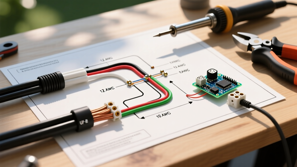
If you are upgrading to a high-flow pump like a Walbro 255 or Aeromotive 340 for a forced-induction Vortec build, the factory 12 AWG Gray wire is sufficient for draws up to 15 amps. However, if your pump exceeds 15 amps, you must bypass the factory harness. Run a new 10 AWG power wire directly from the battery via a 30-amp relay, triggered by the factory Gray wire, and use a dedicated 10 AWG ground to the chassis. For high-quality terminals and relays, consult the Standard Motor Products eCatalog to match OEM-spec connector housings.