
Panel Integration: Control & Step-Down Transformer Wiring
When building or retrofitting an industrial control panel or commercial distribution board, integrating a transformer requires strict adherence to overcurrent protection and grounding rules. Whether you are stepping down 480V to 120/240V for a sub-panel or dropping 240V to 24V for control relays, finding the correct wiring diagram for transformer integration is only the first step. The real challenge lies in breaker sizing, wire gauge selection, and managing magnetizing inrush current.
In this 2026 Panel & Breaker Guide, we break down the exact wiring topologies, NEC Article 450 compliance matrices, and physical mounting clearances for the most common panel transformers, including the industry-standard Schneider Electric Square D 9070T500D1 (500VA) and Hammond Manufacturing 5kVA step-down units.
2026 Market Pricing & Availability
As of early 2026, supply chain stabilization has normalized industrial transformer pricing. Expect to pay between $165 and $210 for a premium 500VA enclosed control transformer (like the Square D 9070 series), while 5kVA single-phase distribution transformers (e.g., Eaton or Hammond) typically range from $1,150 to $1,450. Always factor in an additional $40-$80 for DIN-rail mounting brackets or panel backplate standoffs.
Core Wiring Diagram for Transformer Types in Panels
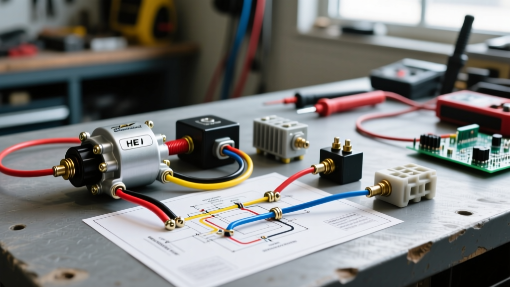
Because physical schematics vary by enclosure, we use a standardized terminal matrix to represent the wiring diagram for transformer connections. Below is the logic for a standard single-phase control transformer with dual primary and dual secondary coils.
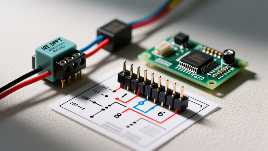
Terminal Matrix: 500VA Control Transformer (240x480V Primary to 24x48V Secondary)- Primary (High Voltage): H1, H2, H3, H4
- Secondary (Low Voltage): X1, X2, X3, X4
For 240V Primary Input: Jumper H1 to H3. Jumper H2 to H4. Apply Line 1 to H1/H3 node. Apply Line 2 to H2/H4 node.
For 24V Secondary Output: Jumper X1 to X3. Jumper X2 to X4. Output 24V across X1/X3 and X2/X4.
Breaker Sizing & Overcurrent Protection (NEC 450.3)
The most common failure in panel builds is nuisance tripping on the primary side. Transformers draw a massive magnetizing inrush current (often 10 to 15 times the full load amperage) for the first few AC cycles upon energization. Standard thermal-magnetic breakers will interpret this as a short circuit and trip immediately.
According to the NFPA 70 National Electrical Code, Table 450.3(B) dictates maximum overcurrent protective device (OCPD) ratings. For primary currents under 9 amps, you are permitted to size the breaker up to 500% of the primary current to accommodate inrush, provided the secondary is protected at 125%.
| Transformer VA | Primary Voltage | Primary FLA | Max Primary OCPD (NEC 450.3B) | Secondary Voltage | Secondary FLA | Secondary OCPD |
|---|---|---|---|---|---|---|
| 500VA | 240V | 2.08A | 6A (or 10A Time-Delay Fuse) | 24V | 20.8A | 25A or 30A |
| 1.5kVA | 480V | 3.12A | 15A (HID Rated Breaker) | 120V | 12.5A | 15A |
| 5kVA | 480V | 10.4A | 15A (Next standard size above 125%) | 120/240V | 20.8A / 41.6A | 45A (Main) |
The Inrush Current Edge Case
If your 500VA transformer is tripping a 6A breaker on startup, do not simply upsize the breaker to 10A, as this violates the wire ampacity rules for 14 AWG. Instead, switch to a High Inrush Discrimination (HID) breaker, such as the Eaton BAB1015H, or use a Class RK5 time-delay fuse (e.g., Bussmann FRS-R-6) on the primary side. This allows the magnetic surge to pass without compromising the thermal protection of the wire.
Wire Gauge Selection & Terminal Torque Specifications
Proper wire sizing must account for both the OCPD rating and the physical terminal limits of the transformer. Control transformers typically feature rising-clamp screw terminals designed for copper conductors only.
- Primary Side (500VA, 6A Breaker): Use 14 AWG THHN or MTW wire. Strip insulation to 5/16 inch. Torque terminal screws to exactly 12 in-lbs. Over-torquing will strip the brass threads; under-torquing causes high-resistance heating and eventual terminal melting.
- Secondary Side (24V, 30A Breaker): Use 10 AWG stranded wire with ferrule crimps. Torque to 15 in-lbs. Because 24V DC/AC systems suffer from severe voltage drop, keep secondary wire runs to the contactors under 15 feet.
Separately Derived Systems (SDS) & Grounding Rules
When wiring a step-down distribution transformer (e.g., 480V to 120/240V) to feed a new sub-panel, you are creating a Separately Derived System (SDS). The OSHA Electrical Safety Standards and NEC Article 250.30 require a specific grounding topology that differs from standard sub-panels.
Step-by-Step SDS Grounding Matrix
- System Bonding Jumper: You must install a bonding jumper on the secondary side of the transformer, connecting the neutral bus (X2/X3) directly to the ground bus. Size this jumper according to NEC Table 250.102(C)(1) based on the secondary ungrounded conductor size.
- Grounding Electrode Conductor (GEC): Run a GEC from the transformer's secondary neutral/ground bond point to the nearest effectively grounded building steel or a dedicated grounding electrode. For a 5kVA transformer using 8 AWG secondary phase conductors, the minimum GEC size is 8 AWG copper.
- Equipment Grounding Conductor (EGC): Run a separate EGC from the primary panel's ground bus to the transformer enclosure to clear primary-side faults.
Expert Warning: Never bond the neutral and ground in a sub-panel fed by a transformer if you have already established the SDS bond at the transformer itself. Doing so creates parallel neutral paths, causing objectionable current to flow on the equipment grounding conductors.
Physical Mounting & Heat Dissipation
Transformers are highly efficient but still generate significant heat. A standard 500VA control transformer operating at full load can experience a 115°C temperature rise in its core. To comply with UL 508A and DOE efficiency guidelines, you must maintain strict physical clearances inside the panel enclosure.
- Top Clearance: Minimum 6 inches above the transformer to allow for convective cooling. Do not route wire ducts directly over the core.
- Side Clearance: Minimum 3 inches to adjacent heat-producing devices like variable frequency drives (VFDs) or solid-state relays.
- Backplate Mounting: Use 1-inch standoffs to allow air circulation behind the unit. Mounting it flush against a steel backplate will trap heat and degrade the winding insulation over time.
Common Failure Modes & Troubleshooting
Even with a perfect wiring diagram for transformer integration, real-world edge cases occur. Here is how to diagnose the three most common panel transformer failures:
- Secondary Voltage is 0V but Primary Breaker Holds: Check the internal thermal fuse. Many modern Hammond and Square D control transformers feature a non-replaceable internal thermal cutoff embedded in the primary winding. If the transformer overheated due to a sustained secondary overload, this fuse blows permanently. Replace the unit.
- Humming or Buzzing Noise: A loud 60Hz hum usually indicates loose laminations in the core or that the transformer is being operated at a lower frequency than designed (e.g., feeding a 60Hz transformer with 50Hz power). It can also occur if the mounting bolts on the backplate are vibrating against the enclosure.
- Premature Breaker Degradation: If you are using standard breakers to switch the transformer on and off daily (instead of a dedicated contactor), the repeated inrush arcs will pit the breaker contacts. Within 12 to 18 months, the breaker will fail to hold. Always use a contactor for high-cycling transformer loads.
By combining the correct wiring topology with precise OCPD sizing and SDS grounding practices, your panel builds will pass inspection on the first attempt and operate reliably for decades.