
Decoding the Blueprint: Schematics vs. Physical Wiring Diagrams
When a residential circuit fails, guessing which wire goes where is a recipe for a blown breaker, damaged equipment, or a severe arc flash. Professional electricians rely on electrical diagrams for house wiring to systematically isolate faults. However, not all diagrams serve the same purpose. To troubleshoot effectively, you must understand the distinction between a schematic diagram and a physical wiring diagram.
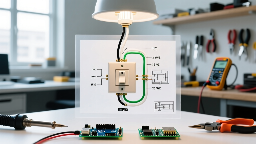
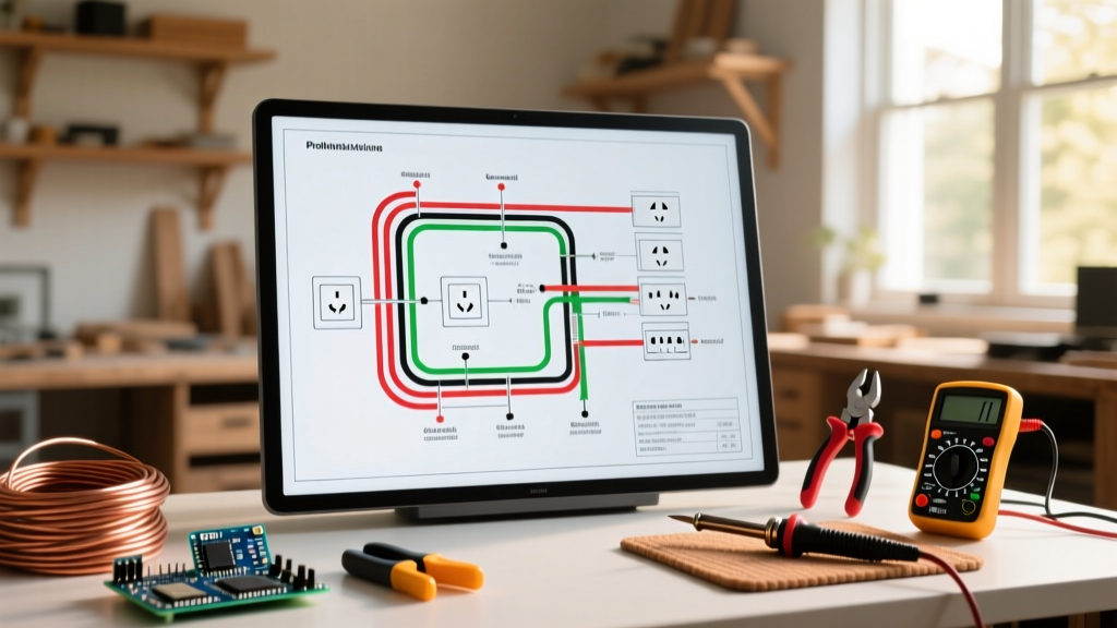
A schematic diagram illustrates the logical flow of electricity. It uses standardized symbols to show how components interact, ignoring their physical location. Schematics are invaluable for understanding control logic, such as a 3-way switch network or a hardwired HVAC control board. Conversely, a wiring diagram (or connection diagram) maps the physical routing of cables, showing exactly which terminal connects to which wire nut inside a specific junction box. For residential troubleshooting, you often need to mentally translate the schematic logic into the physical reality of the wiring diagram to locate a hidden fault.
The Troubleshooter’s Symbol Glossary
Before tracing a fault, you must fluently read the legend. The National Electrical Code (NEC) and standard architectural drafting practices dictate specific symbols for residential plans. Below is a reference table for the most critical symbols you will encounter when diagnosing household circuits.
| Symbol | Component | Troubleshooting Context & Failure Modes |
|---|---|---|
| $ (Circle with S) | Single-Pole Switch | Verify line/load orientation. Reversed polarity causes smart switches to malfunction or fail to power down. |
| S3 | 3-Way Switch | Identify the 'common' terminal. Faults usually occur on the traveler wires or miswired common terminals. |
| ⊗ | Ceiling Fan / Motor | Check for capacitor failure or binding bearings if the motor draws >120% of its Full Load Amps (FLA). |
| GFCI | Ground Fault Receptacle | Ensure the 'LOAD' terminals are used for downstream protection. Line/Load reversal disables GFCI protection. |
| AFCI | Arc-Fault Breaker | Check for shared neutrals downstream, which cause immediate nuisance tripping upon load activation. |
Step-by-Step Fault Tracing Protocol
Reading electrical diagrams for house wiring is only half the battle; executing a safe, methodical diagnostic protocol is the other. As of the 2026 NEC cycle, strict adherence to Lockout/Tagout (LOTO) and verified dead-circuit testing is non-negotiable. According to OSHA Electrical Safety Guidelines, failure to verify the absence of voltage before touching conductors remains a leading cause of residential electrical injuries.
Phase 1: Isolate and Verify (Dead Circuit)
- Panel Mapping: Cross-reference the panel schedule with your wiring diagram. Identify the specific breaker controlling the faulted zone.
- LOTO Execution: Switch off the breaker and apply a physical lockout tag.
- Live-Dead-Live Test: Use a Category III (CAT III) rated multimeter. Test the meter on a known live source (e.g., a verified 120V outlet), test the target circuit to confirm 0V, then re-test the known live source to ensure the meter didn't fail during the process.
- Continuity Tracing: With the circuit dead, use the diagram to identify junction points. Measure continuity between the panel neutral bus and the receptacle neutral slot. An open reading indicates a broken wire, a pushed-out backstab connection, or a missing wire nut.
Phase 2: Energized Diagnostics (Live Circuit)
If the dead-circuit continuity checks pass, the fault may only manifest under load. Energize the circuit and perform voltage drop tests. NEC Informational Note 210.19 recommends a maximum 3% voltage drop for branch circuits. If you measure 112V at the receptacle under a 12A load (like a space heater), but 121V at the panel, you have a high-resistance connection—likely a corroded wire nut or a failing backstabbed terminal—somewhere along the diagram's routed path.
Advanced Failure Modes & Diagram Mapping
Basic open and short circuits are easy to spot on a diagram. True expertise lies in diagnosing complex, code-specific failure modes that aren't immediately obvious from a visual inspection.
The Multi-Wire Branch Circuit (MWBC) Shared Neutral Overload
An MWBC uses two hot wires (on opposite phases) and one shared neutral to supply two 120V circuits. On a wiring diagram, this is shown as a 3-wire cable (e.g., 14/3 Romex) leaving the panel. The Hazard: If a previous DIYer replaced the original 2-pole breaker with two single-pole breakers placed on the same phase leg, the neutral wire will carry the sum of both currents (e.g., 15A + 15A = 30A). The 14 AWG neutral wire will overheat inside the wall long before a 15A breaker trips. The Fix: Use the diagram to trace the 3-wire cable and verify NEC 210.4 compliance by installing a handle-tie or a dedicated 2-pole breaker to ensure opposite-phase legs.
AFCI Nuisance Tripping and Phantom Loads
Combination Arc-Fault Circuit Interrupters (CAFCI) are highly sensitive. A common troubleshooting scenario involves a CAFCI breaker tripping when a vacuum cleaner or power drill is turned on. Universal motors naturally create brush arcing, which the CAFCI misinterprets as a dangerous parallel arc fault. Furthermore, if your wiring diagram shows multiple circuits sharing a physical junction box, ensure the neutrals are strictly isolated. A downstream neutral-to-ground fault or a shared neutral between two CAFCI circuits will cause immediate tripping. As noted in CPSC Electrical Fire Safety reports, while AFCIs drastically reduce electrical fires, improper installation and shared neutrals remain the primary cause of nuisance tripping complaints.
Phantom Voltage and Induced EMF
When troubleshooting a switched loop, you might measure 40V to 70V on a disconnected wire using a high-impedance digital multimeter (10MΩ). This is 'ghost voltage' caused by capacitive coupling from adjacent live wires in the same cable bundle. It can lead an inexperienced tech to believe a circuit is live when it is actually open. To resolve this, switch your multimeter to Low Impedance (LoZ) mode, which places a small load on the circuit to bleed off the phantom voltage, confirming a true 0V open circuit.
Expert Insight: Never rely solely on non-contact voltage testers (NCVTs) for final fault isolation. NCVTs detect electromagnetic fields, not actual voltage potential, and are highly susceptible to false positives from static buildup or adjacent live circuits in dense residential panels.
Diagnostic Tool Loadout for Diagram-Based Troubleshooting
To accurately map physical reality against your electrical diagrams for house wiring, you need precision instruments. Here is the 2026 professional loadout with current market pricing:
- Fluke 117 True RMS Multimeter ($210 - $230): The industry standard. Features AutoVolt and LoZ modes to eliminate ghost voltage readings during continuity mapping.
- Klein Tools MM700 Digital Multimeter ($60 - $75): A highly capable, budget-friendly alternative for advanced DIYers, featuring CAT III 1000V safety ratings and built-in NCVT.
- Amprobe AT-3500 Advanced Cable Tracer ($350 - $400): Essential for tracing concealed branch circuits through drywall when the physical wiring diagram is missing or inaccurate. It can trace breakers and identify specific wire pairs in a bundle.
- Greenlee 830 Digital Circuit Breaker Finder ($45 - $55): Quickly maps receptacles to panel breakers, allowing you to verify the accuracy of the panel schedule before opening junction boxes.
Symptom-to-Diagram Troubleshooting Matrix
Use this rapid-reference matrix to correlate physical symptoms with specific diagram checkpoints. For deeper diagnostic methodologies, refer to the Fluke Electrical Troubleshooting Resources library.
| Observed Symptom | Diagram Checkpoint | Probable Root Cause & Action |
|---|---|---|
| Receptacle works, but GFCI test button does not trip. | Verify Line vs. Load terminal mapping on the GFCI device. | Line/Load reversed. Power is bypassing the internal sensor coil. Swap wires. |
| Lights dim momentarily when the refrigerator compressor kicks on. | Check if lighting and appliance circuits share a neutral or breaker. | Voltage drop due to undersized wire or shared circuit. Run a dedicated 20A line. |
| 3-Way switch only works from one location. | Trace traveler wires between Switch A and Switch B. | Open traveler wire or misidentified 'Common' screw on the replacement switch. |
| Breaker trips instantly upon reset, no load connected. | Inspect diagram for hard short (Hot-to-Ground or Hot-to-Neutral). | Nail/screw through cable, melted wire insulation, or water in an exterior junction box. |
Final Thoughts on Residential Diagnostics
Mastering electrical diagrams for house wiring transforms troubleshooting from a dangerous guessing game into a precise, scientific process. By combining a deep understanding of schematic logic with modern, high-impedance testing equipment, you can isolate hidden faults, ensure NEC compliance, and maintain the safety of the residential electrical system. Always prioritize verified dead-circuit testing, respect the physical limitations of wire gauges, and never assume a previous installer followed the original blueprint.