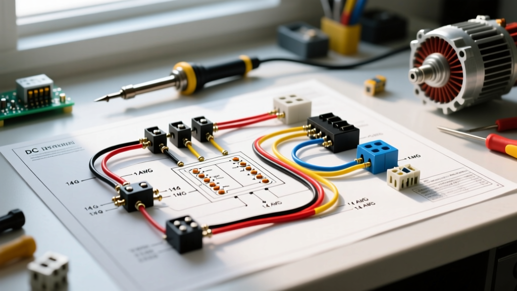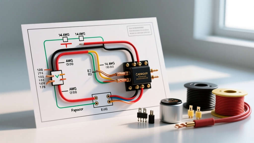

The Evolution of Electrical Fuse Box Wiring
When homeowners and DIYers research electrical fuse box wiring, they are often dealing with legacy systems. True Edison-base or Type-S fuse panels have largely been phased out in favor of modern thermal-magnetic circuit breaker panels. However, the fundamental principles of wire gauge selection, ampacity limits, and conductor color coding remain identical whether you are maintaining an older 60-amp fuse box, upgrading to a 200-amp breaker panel, or wiring a new subpanel. As we navigate the 2023 and upcoming 2026 National Electrical Code (NEC) cycles, the emphasis on precise torque specifications and strict color-coding has never been higher. Improperly sized conductors or misidentified neutrals in a panelboard are leading causes of thermal runaway and residential electrical fires.
This comprehensive reference guide bridges the gap between theoretical code and practical panelboard wiring, giving you the exact specifications needed to route, terminate, and identify conductors safely.
Wire Gauge Selection: The Backbone of Panel Safety
The most critical aspect of any electrical fuse box wiring project is matching the wire gauge (AWG) to the overcurrent protection device (OCPD) rating. The NEC strictly prohibits upsizing a breaker without upsizing the wire. Furthermore, ampacity is heavily dependent on the insulation temperature rating. While THHN/THWN-2 wire is rated for 90°C in conduit, NEC Article 110.14(C) dictates that for circuits rated 100 amps or less, the ampacity must be calculated using the 60°C column of NEC Table 310.16, unless the equipment terminals are explicitly rated for 75°C.
Below is the definitive reference table for standard copper conductor sizing in residential and light commercial panelboards.
| Wire Gauge (AWG) | Standard Breaker/Fuse Size | 60°C Ampacity Limit | Max Continuous Load (80% Rule) | Common NM-B Jacket Color |
|---|---|---|---|---|
| 14 AWG | 15 Amps | 15 Amps | 12 Amps (1,440W @ 120V) | White |
| 12 AWG | 20 Amps | 20 Amps | 16 Amps (1,920W @ 120V) | Yellow |
| 10 AWG | 30 Amps | 30 Amps | 24 Amps (2,880W @ 120V) | Orange |
| 8 AWG | 40 Amps | 40 Amps | 32 Amps (3,840W @ 240V) | Black |
| 6 AWG | 55 / 60 Amps | 55 Amps | 44 Amps (5,280W @ 240V) | Black |
| 4 AWG | 70 Amps | 70 Amps | 56 Amps (13,440W @ 240V) | Black |
| 3 AWG | 100 Amps | 100 Amps | 80 Amps (Subpanel Feed) | Black |
Note: For 60-amp circuits using 6 AWG copper, the breaker must be rated 60A, but the 60°C ampacity limit is technically 55A. The NEC allows the next standard size up (60A) per Article 240.4(B). For strict 60A continuous loads, 4 AWG is required.
Decoding NM-B and THHN Color Codes
Color coding in electrical fuse box wiring serves two distinct purposes: identifying the jacket of non-metallic (NM-B) cables and identifying individual conductors inside conduit (THHN/THWN-2). Confusing these two systems is a common pitfall for apprentices.
1. NM-B (Romex) Outer Jacket Colors
Manufacturers color-code the outer sheathing of NM-B cables to allow inspectors and electricians to instantly verify the wire gauge before the jacket is even stripped.
- White Jacket: 14 AWG (15A circuits, basic lighting)
- Yellow Jacket: 12 AWG (20A circuits, kitchen/bath receptacles)
- Orange Jacket: 10 AWG (30A circuits, water heaters, dryers)
- Black Jacket: 8 AWG and 6 AWG (40A-60A circuits, ranges, subpanels)
2. Individual Conductor Insulation Colors
Once inside the panelboard, the individual wire insulation colors dictate the conductor's function. The NFPA 70 (NEC) mandates strict adherence to these color assignments to prevent cross-wiring and ground faults.
- Black, Red, Blue, Yellow: Ungrounded (Hot) conductors. In a 240V split-phase panel, Black and Red are typically used for the two hot legs. Blue and Yellow are reserved for 3-phase systems or switched legs.
- White or Gray: Grounded (Neutral) conductor. Must terminate exclusively on the neutral bus bar. Re-identifying a white wire as a hot conductor with black tape is permitted in conduit runs (NEC 200.7), but never permitted inside NM-B cables for standard 120V circuits.
- Bare Copper or Green: Equipment Grounding Conductor (EGC). Must terminate on the grounding bus bar. In main service panels, the neutral and ground bars are bonded; in subpanels, they must remain strictly isolated.
Termination Protocols and Torque Specifications
The physical connection of the wire to the breaker lug or bus bar is where most electrical fuse box wiring failures occur. A loose connection increases electrical resistance, generating excess heat that can melt the breaker casing or ignite surrounding insulation.
NEC 110.14(D) Mandate: "Terminals for more than one conductor and terminals used to connect aluminum shall be so identified. Terminals shall be torqued to the manufacturer's specified values using a calibrated torque tool."
Gone are the days of "tightening until it feels snug." Modern panel manufacturers like Square D, Siemens, and Eaton print exact torque specifications directly on the panelboard label. For standard 15A and 20A plug-on or bolt-on breakers, the typical torque requirement ranges from 20 to 25 inch-pounds. Larger 100A main breaker lugs often require 40 to 50 inch-pounds or more. Always use a certified, click-type torque screwdriver (such as those from CDI or Wiha) to ensure compliance and safety.
Proper Wire Stripping and Seating
- Strip Length: Use the strip gauge printed on the breaker. Typically, this is 3/8" to 1/2" for 14-10 AWG, and 5/8" to 3/4" for 8-4 AWG.
- No Exposed Copper: The insulation should rest flush against the plastic barrier of the breaker lug. Exposed copper outside the lug creates a shock hazard and risks shorting against adjacent grounded metal.
- No Insulation Under the Lug: Conversely, do not strip too little wire. If the screw clamps down on the plastic insulation rather than the copper conductor, the connection will fail under load.
Troubleshooting Edge Cases in Older Panels
When working on legacy electrical fuse box wiring or early breaker panels, you will inevitably encounter code violations that must be rectified. Here are the most common edge cases and how to handle them.
The "Double-Tapped" Neutral
It is common to find two or even three white neutral wires crammed under a single screw on the neutral bus bar. NEC 408.41 strictly prohibits this. While some specific breaker models (like certain Square D QO or Homeline breakers) are UL-listed to accept two hot conductors under a single lug, neutral bus bars are almost never rated for double-tapping. The Fix: Install an additional neutral bus bar (if space permits) or use a wire nut to pigtail the neutrals, ensuring only one conductor terminates under the bus bar screw.
Aluminum to Copper Transitions
During the 1970s, copper prices spiked, leading to the widespread use of aluminum branch circuit wiring. If you are integrating modern copper breakers into a panel fed by older aluminum service entrance cables, the breaker lugs must be explicitly rated CU/AL. Furthermore, you must apply an anti-oxidant compound (such as Noalox or Penetrox) to the aluminum strands before termination to prevent galvanic corrosion and thermal expansion issues.
Frequently Asked Questions
Can I use 12 AWG wire on a 15-amp breaker?
Yes. The NEC allows you to use a wire gauge rated for a higher amperage than the breaker. Using 12 AWG (20A rated) on a 15A breaker is perfectly safe and is actually a common practice to reduce voltage drop on long circuit runs exceeding 50 feet. However, you must ensure the 12 AWG wire physically fits into the breaker's lug; some older 15A breakers are not rated to accept 12 AWG solid copper.
Why are there two ground bars in my panel?
Manufacturers often install a main neutral/ground bar on one side and an auxiliary ground bar on the other to save space and reduce wire clutter. According to the Copper Development Association and NEC guidelines, these auxiliary bars are bonded to the panel enclosure, which is ultimately bonded to the main neutral. You can safely terminate bare ground wires on these auxiliary bars, but never terminate white neutral wires on them.
What is the bending radius for wires inside a panel?
NEC Article 312.6 requires adequate space for wiring. Conductors must not be bent to a radius less than specified in Table 312.6(B). For standard 14-10 AWG wires, maintain a gentle curve. Forcing wires into sharp 90-degree angles directly at the breaker lug can stress the copper, causing microscopic fractures that lead to high-resistance hot spots over time.
For further reading on residential electrical safety and panel clearances, refer to the OSHA general electrical requirements and your local municipal building codes, which may enforce amendments stricter than the baseline NEC.