
Mastering the Wiring Diagram for GE Dryer Timer Replacements
A malfunctioning dryer timer is one of the most common reasons a General Electric (GE) dryer will either run continuously without shutting off, fail to advance through cycles, or refuse to produce heat. For DIY technicians and homeowners, navigating the wiring diagram for GE dryer timer circuits can feel overwhelming due to the dense network of color-coded wires, terminal spades, and interlocking safety switches. However, with a systematic approach, replacing and rewiring a GE timer—specifically the ubiquitous mechanical WE4M533 or the newer electronic WE04X27224 control boards—is a highly manageable task.
According to the National Fire Protection Association (NFPA), washing machines and dryers are responsible for thousands of residential fires annually, with electrical failures and improper wiring being leading culprits. This guide provides a deep-dive, step-by-step wiring walkthrough to ensure your repair is both functional and compliant with modern electrical safety standards.
Mechanical vs. Electronic GE Timer Architectures
Before touching a single wire, you must identify which timer architecture your GE dryer utilizes. The wiring diagrams and diagnostic approaches differ vastly between the two primary systems found in GE dryers from the early 2000s through 2026.
The Mechanical Timer (e.g., GE WE4M533)
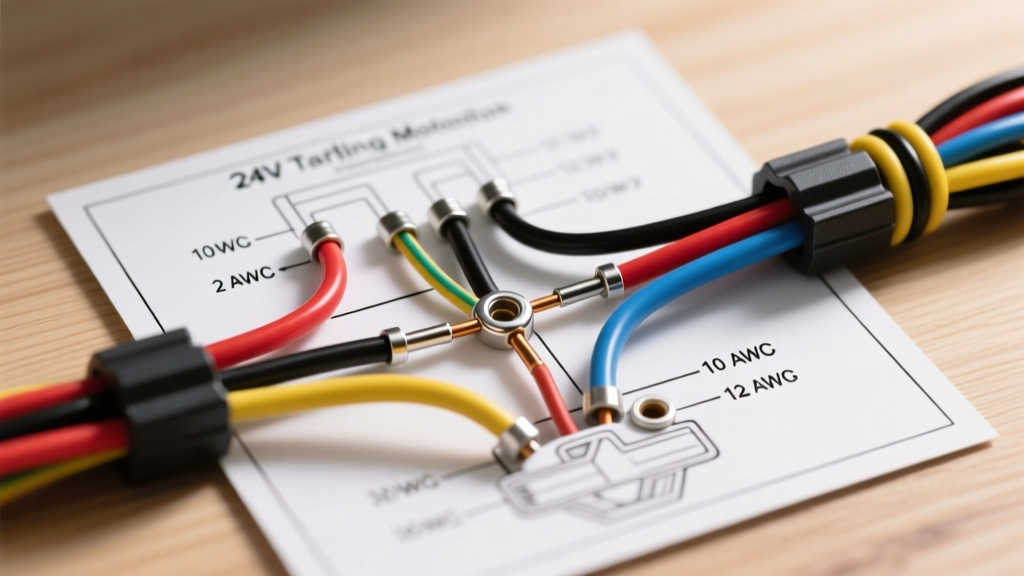
Found in most standard, non-smart GE electric and gas dryers, the mechanical timer relies on a synchronous motor that turns a series of brass cams. These cams physically open and close electrical contacts to route 240V line voltage and 120V control voltage to the heater assembly, drive motor, and cycling thermostat. The wiring harness connects via individual 1/4-inch female spade connectors directly to a Bakelite terminal board on the back of the timer.
The Electronic Control Board (e.g., GE WE04X27224)
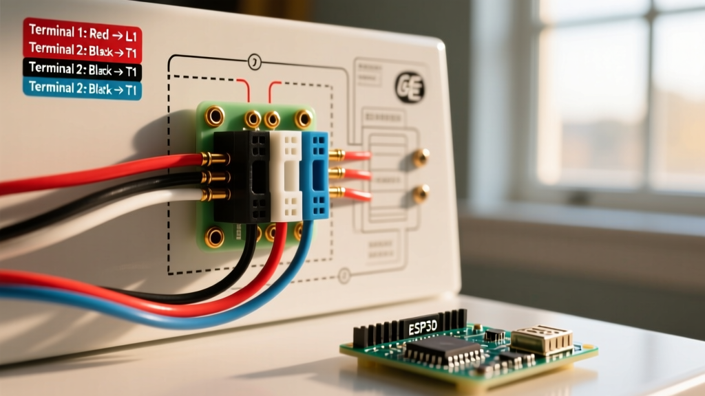
Modern GE Profile and smart dryers utilize electronic control boards. Instead of individual spade wires routing high voltage, these boards use low-voltage ribbon cables, thermistors, and solid-state relays (triacs) to manage cycles. If you are working on an electronic board, you will not be referencing a traditional spade-terminal wiring diagram; instead, you will be checking continuity across ribbon harness pins and testing thermistor resistance (typically 10k ohms at 77°F).
Expert Insight: If your GE dryer has a physical dial that you must turn to start the cycle, you are working with a mechanical timer. If it features a digital push-button interface, you are dealing with an electronic control board. This walkthrough focuses heavily on the mechanical timer, as it requires the most rigorous manual wiring mapping.
GE Mechanical Timer Terminal Mapping Matrix
The GE WE4M533 mechanical timer features a specific terminal layout. While wire colors can occasionally vary based on the exact manufacturing year and whether the unit is gas or electric, the terminal letter designations remain standardized across the platform. Below is the definitive terminal mapping matrix for a standard GE electric dryer timer.
| Terminal ID | Typical Wire Color | Function / Destination | Voltage State |
|---|---|---|---|
| T | Black or Red | L1 Line Voltage Input (from power cord/timer switch) | 120V AC (Constant) |
| C | Red w/ White Stripe | Motor Centrifugal Switch (Start/Run winding) | 120V AC (Switched) |
| H | Red or Orange | Heater Assembly / Gas Valve Operator | 120V/240V (Switched) |
| A | Blue | Timer Synchronous Motor (Advances the dial) | 120V AC |
| B | Orange or Purple | Cycling Thermostat (Regulates drum heat) | Control Circuit |
| X | White or Yellow | Door Switch / Push-to-Start Switch Return | Neutral / Return |
Step-by-Step Wiring Walkthrough: Replacing the WE4M533
Replacing the timer requires precision. A single misplaced wire can result in a dead short, a blown thermal fuse, or a dryer that heats while the door is open—a severe hazard flagged by the Consumer Product Safety Commission (CPSC).
Step 1: Lockout/Tagout (LOTO) and Voltage Verification
Never rely solely on the dryer's control panel to confirm power is off. Electric dryers operate on a 240V split-phase circuit. Locate your main electrical panel and flip the double-pole 30-amp breaker to the OFF position. Use a CAT III or CAT IV rated multimeter (such as the Fluke 117) to test the dryer's terminal block at the back of the machine. Measure L1 to L2 (should read 0V), L1 to Ground (0V), and L2 to Ground (0V).
Step 2: Console Disassembly
- Remove the two or three Phillips-head screws located on the back of the control console endcaps.
- Slide a plastic putty knife under the front edge of the console to release the hidden spring clips.
- Gently roll the console backward on its hinges to expose the back of the timer and the main wiring harness.
Step 3: The 'One-Wire-At-A-Time' Transfer Method
While GE Appliances Official Support provides schematic PDFs for every model, the most fail-safe method for DIYers is the one-wire transfer technique. Do not pull all wires off the old timer at once.
- Use needle-nose pliers to grip the metal barrel of the female spade connector, not the plastic insulation.
- Pull the wire straight off Terminal 'T' on the old timer.
- Immediately push it onto Terminal 'T' on the new WE4M533 timer until you feel the brass detent click into place.
- Repeat this process sequentially through terminals C, H, A, B, and X.
Step 4: Inspecting for Carbon Tracking and Thermal Damage
Before fully seating the new timer, inspect the female spade connectors on the wiring harness. The 'H' (Heater) and 'T' (Line) terminals carry the highest current. If you see black soot, melted plastic, or green corrosion (carbon tracking), the connector is compromised. Cut the damaged spade off, strip exactly 1/4-inch of insulation using a precision wire stripper, and crimp on a new 16-14 AWG fully insulated female disconnect. Failing to replace burnt connectors will cause the new timer to fail prematurely due to increased electrical resistance and arcing.
Step 5: Harness Dressing and Reassembly
Route the wires exactly as they were originally dressed. Ensure no wires are resting against the sharp edges of the sheet metal console or the rotating brass cams of the timer. A wire rubbing against the timer motor housing will eventually short out, tripping your home's breaker. Secure the harness with high-temperature nylon zip ties if the original plastic retaining clips are broken.
Common Failure Modes and Edge Cases
Even with a perfect wiring diagram execution, you must understand why the timer failed to prevent a repeat issue.
1. The Timer Motor vs. Centrifugal Switch Conflict
A frequent edge case occurs when the dryer runs, but the timer never advances, even though the new timer motor (Terminal A) is receiving 120V. This is often caused by a faulty centrifugal switch on the main drive motor. The timer motor circuit is wired in parallel with the drive motor's start winding. If the drive motor's centrifugal switch sticks in the 'start' position, it drops the voltage available to the timer motor, preventing it from turning. Always test the drive motor switch continuity if a new timer fails to advance.
2. Internal Contact Pitting (No Heat Condition)
If the timer advances perfectly but the dryer produces zero heat, the internal brass contacts for the 'H' terminal inside the timer housing may be pitted or fused open. Because the timer casing is sealed and non-serviceable, internal pitting requires a complete unit replacement. Do not attempt to drill into the Bakelite housing to clean contacts.
3. Camshaft Wear and Knob Slippage
If the timer knob spins freely without engaging the internal mechanism, the D-shaped plastic shaft on the knob or the metal camshaft on the timer has stripped. In 90% of cases, replacing the plastic knob (Part #WE01X10310) resolves this for under $15, saving you from replacing the entire timer assembly.
2026 Tool and Parts Cost Breakdown
Budgeting for a GE dryer timer repair in 2026 requires accounting for both the OEM components and the specialized tools needed for a safe repair. Below is a realistic cost matrix for DIYers.
| Item / Component | Part Number / Spec | Estimated 2026 Cost |
|---|---|---|
| OEM Mechanical Timer | GE WE4M533 | $48.00 - $65.00 |
| Timer Knob (D-Shaft) | GE WE01X10310 | $12.00 - $18.00 |
| CAT III Digital Multimeter | Fluke 117 or Klein MM700 | $160.00 - $220.00 |
| 1/4' Hex Nut Driver | Klein Tools 630-4 | $8.00 - $12.00 |
| Insulated Spade Connectors | 16-14 AWG Female (10-pack) | $6.00 - $9.00 |
Final Safety and Testing Protocols
Once the console is reassembled and the dryer is pushed back into position, restore power at the main breaker. Do not immediately load the dryer with wet clothes. Run a 'Timed Dry' cycle on the 'Air Fluff' (no heat) setting for 10 minutes. Listen for the faint, rhythmic humming of the timer motor advancing. Next, switch to a 'Normal' heat cycle and verify that the exhaust air at the exterior vent becomes warm within 3 to 5 minutes. Finally, open the door mid-cycle; the drum must stop spinning and the heating element must instantly de-energize. If the dryer continues to heat with the door open, immediately kill the breaker and re-verify your Terminal 'X' and door switch wiring.
By strictly adhering to the wiring diagram, utilizing the one-wire transfer method, and respecting the 240V environment, you can reliably restore your GE dryer to full operational safety and efficiency.