
Decoding the Schematic: Why the Wiring Diagram for Whirlpool Refrigerator Units Matters
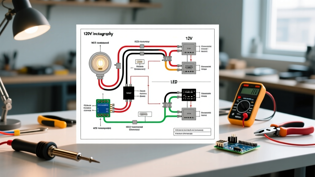
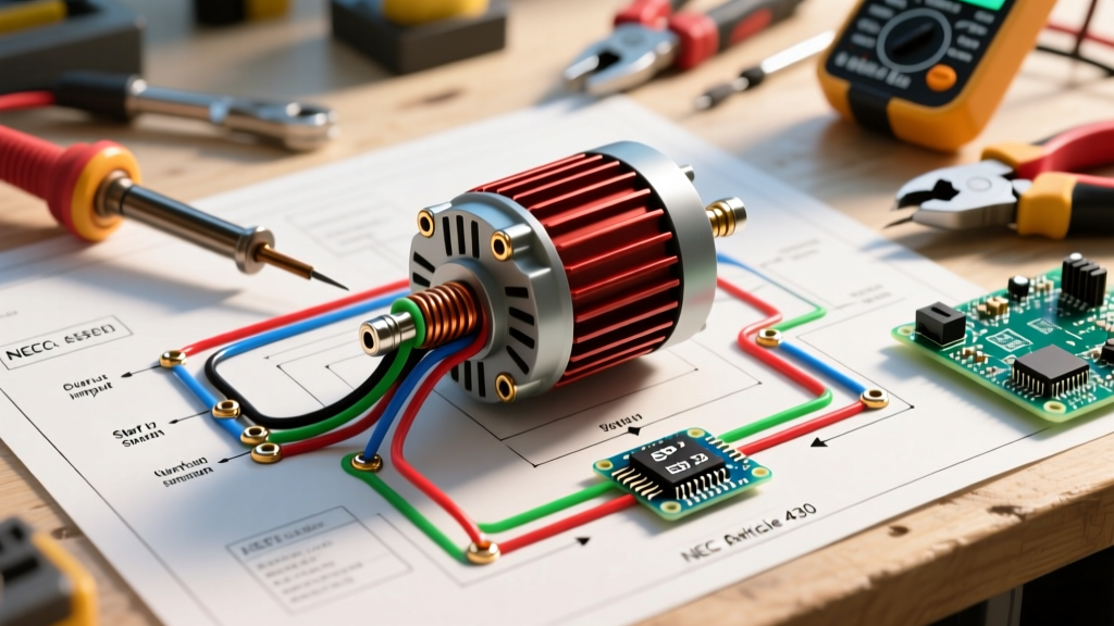
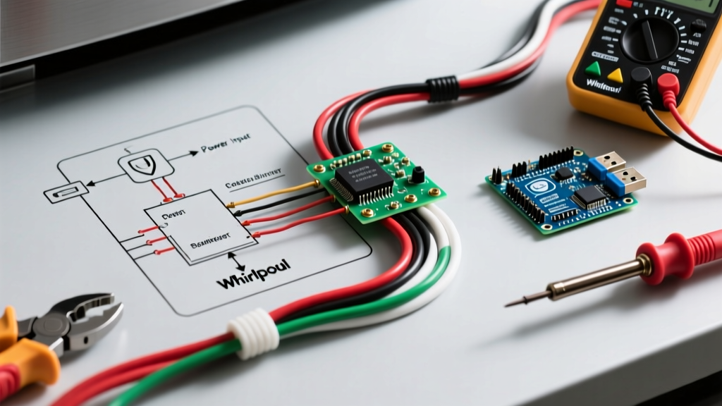
When integrating a major kitchen appliance into your home's electrical panel, relying on generic assumptions is a recipe for nuisance tripping and fire hazards. Modern cooling units are no longer simple compressor-and-thermostat loops. To properly size your breakers and select the correct wire gauge, you must understand the specific wiring diagram for Whirlpool refrigerator models, such as the popular WRF535SMHZ or WRX735SDHZ French Door series. These schematics reveal a complex network of AC line voltage, DC control signals, inverter-driven compressors, and high-draw defrost heaters. According to the U.S. Consumer Product Safety Commission (CPSC), improper circuit sizing and overloaded branch circuits remain a leading cause of residential electrical fires. By mapping the appliance's internal load profile to your panel's breaker capacity, you ensure both operational longevity and strict code compliance.
Breaker Sizing & Panel Requirements: The 20-Amp Dedicated Mandate
A common mistake in older homes is placing the refrigerator on a shared 15-amp lighting or small-appliance circuit. While older top-freezer models might have drawn a mere 3 to 4 amps, modern Whirlpool units feature adaptive defrost algorithms, dual-evaporator systems, and smart-diagnostic control boards that create complex inrush current profiles. The National Fire Protection Association (NFPA 70 / NEC) strongly advocates for dedicated circuits for major appliances to prevent voltage drops that can damage sensitive microprocessors.
Component Load Profile (120V AC System)
Below is a breakdown of the typical amperage draws found on a Whirlpool schematic. Notice that while the running wattage is low, the starting surge and defrost cycles dictate your breaker sizing.
| Component | Function | Running Amps | Peak/Surge Amps | Wire/Relay Spec on Diagram |
|---|---|---|---|---|
| Compressor (e.g., Embraco VEMY) | Refrigerant circulation | 1.2A - 2.5A | 8.0A - 12.0A (LRA) | PTC Start Relay, 12 AWG |
| Defrost Heater | Evaporator ice melting | 3.5A - 4.5A | 4.5A (Resistive) | Series with Bi-Metal Thermostat |
| Evaporator Fan (ECM) | Freezer air circulation | 0.4A - 0.8A | 0.8A | DC Control via Main Board |
| Condenser Fan Motor | Compressor cooling | 0.8A - 1.1A | 2.5A | AC Line, Shaded Pole |
| Main Control Board | Logic & Defrost Timing | 0.1A | N/A | 12V DC Outputs to Sensors |
The Verdict: You must install a dedicated 20-Amp single-pole breaker (such as a Square D HOM120 or Siemens Q120) paired with 12 AWG copper wire (12/2 NM-B Romex). A 15-amp breaker will frequently experience 'nuisance tripping' during the compressor's Locked Rotor Amp (LRA) startup phase, especially if the ambient garage or kitchen temperature is high.
Navigating NEC GFCI Requirements for Kitchen Cooling
One of the most heavily debated topics in the 2026 electrical landscape is Ground Fault Circuit Interrupter (GFCI) protection for refrigerators. The NEC Article 210.8(A)(6) mandates GFCI protection for all 125-volt, single-phase, 15- and 20-ampere receptacles installed to serve kitchen countertops. However, the interpretation of 'countertop' versus 'dedicated appliance' varies by local Authority Having Jurisdiction (AHJ).
Expert Tip: If your Whirlpool refrigerator is located within 6 feet of the kitchen sink, the AHJ will almost certainly require a 20A GFCI receptacle or a GFCI breaker in the panel. To prevent the notorious 'phantom tripping' caused by the defrost heater's minor capacitive leakage to ground, use a high-quality, hospital-grade GFCI receptacle (like the Leviton GFNT2) rather than a GFCI breaker, as receptacles handle localized surge dissipation better than panel-mounted GFCI boards.
Step-by-Step Breaker & Receptacle Wiring Protocol
Follow this exact sequence to wire the dedicated circuit from your main panel to the appliance location, ensuring compliance with National Electrical Manufacturers Association (NEMA) standards for 5-20R receptacles.
- Panel Preparation: Turn off the main breaker. Install the 20A single-pole breaker into an available slot on the bus bar. Ensure the bus bar stab is rated for the breaker's interrupting capacity (typically 10kAIC for residential).
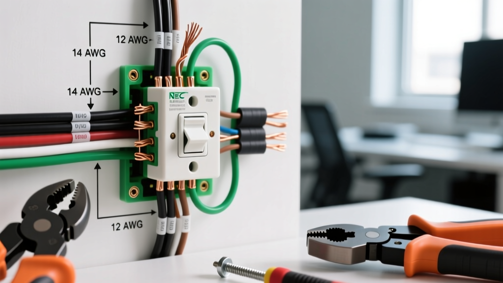
- Wire Stripping & Termination: Strip 5/8 inch of insulation from the 12 AWG black (hot) and white (neutral) wires. Hook the black wire clockwise under the breaker's terminal screw and torque to 12 in-lbs. Connect the white wire to the neutral bar and the bare copper to the ground bar.
- Receptacle Wiring (NEMA 5-20R): At the outlet box, connect the black wire to the brass (hot) terminal, the white wire to the silver (neutral) terminal, and the bare copper to the green ground screw. Use the side-screw terminals rather than the back-stab push-in holes to prevent high-resistance arcing over time.
- Verification: Use a digital multimeter to verify 120V AC (+/- 5V) between hot and neutral, and 0V between neutral and ground before plugging in the Whirlpool unit.
Troubleshooting Nuisance Trips via the Wiring Diagram
When a breaker trips immediately upon plugging in the refrigerator, or randomly during the night, the wiring diagram is your primary diagnostic tool. Here are the three most common failure modes specific to Whirlpool schematics:
1. Defrost Heater Ground Fault (Trips GFCI or Standard Breaker)
The wiring diagram shows the defrost heater in series with the defrost thermostat (bi-metal switch) and controlled by a relay on the main board (e.g., part W11083834). Over time, moisture infiltrates the heater's quartz tube housing. When the board initiates the defrost cycle (usually 300W-500W draw), the compromised insulation leaks current to the chassis ground. If on a GFCI, it trips instantly. Fix: Test the heater for continuity to ground using a megohmmeter. Replace the heater assembly if resistance to ground is below 1 Megaohm.
2. Compressor PTC Start Relay Failure (Trips Thermal Breaker)
The schematic routes L1 through the overload protector and into the Positive Temperature Coefficient (PTC) start relay. If the PTC relay shatters internally due to heat fatigue, it fails to drop out the start winding. The compressor runs on both start and run windings simultaneously, drawing 15+ amps continuously. A 20A breaker's thermal bimetallic strip will heat up and trip the circuit after 3 to 5 minutes. Fix: Pull the relay off the compressor pins (C, S, R). Shake it; if it rattles like a maraca, it is destroyed. Replace with the exact OEM Whirlpool relay part number.
3. Condenser Fan Motor Short (Magnetic Trip)
If the breaker trips with a loud 'snap' the exact millisecond the compressor kicks on, you are experiencing a magnetic (short-circuit) trip, not a thermal overload. The diagram links the condenser fan motor in parallel with the compressor run circuit. If the fan motor's internal windings short to the stator casing, it creates a dead short to ground, pulling hundreds of amps instantly. Fix: Disconnect the fan motor harness at the main board and test the compressor independently. If the compressor runs fine, replace the condenser fan motor.
2026 Material Cost Breakdown for Panel Upgrades
If your current panel lacks capacity or you need to run a new dedicated line, here is the realistic material cost for a 2026 installation (assuming a 50-foot wire run):
- 12/2 NM-B Romex (250ft spool): $115.00 - $130.00
- Square D Homeline 20A Single-Pole Breaker: $6.50 - $8.00
- Leviton 20A Hospital-Grade Receptacle: $12.00 - $15.00
- Heavy-Duty Steel Single-Gang Outlet Box: $3.50
- Total Material Cost: ~$137.00 - $156.50 (excluding drywall repair and panel knockouts)
Understanding the intricate pathways of the wiring diagram for Whirlpool refrigerator systems transforms a guessing game into a precise, code-compliant electrical installation. By respecting the inrush currents, isolating the circuit on a dedicated 20-amp breaker, and utilizing the schematic to pinpoint ground faults, you guarantee that your kitchen's most critical appliance operates flawlessly for its entire 12-to-15-year lifespan.