
The Critical Role of Diagrams in 240V Spa Diagnostics
When a 50A or 60A 2-pole GFCI breaker trips immediately upon resetting, the hot tub is essentially dead in the water. As of the 2026 National Electrical Code (NEC) updates, strict adherence to NEC Article 680 mandates rigorous ground-fault protection for all spa equipment. However, a tripped breaker is merely a symptom. To isolate the root cause—whether it is a degraded heater element, a failing ozone generator, or moisture intrusion in the topside panel—you must systematically navigate the wiring diagram for a hot tub.
Modern control systems, such as the Balboa Water Group BP501G1 or the Gecko Alliance Y-Series, rely on complex solid-state relays and modular terminal blocks. Guessing which wire to pull can lead to catastrophic board failure or lethal shock. This guide provides a masterclass in using your spa's schematic to perform methodical component isolation.
WARNING: Lethal Voltage Hazard. A hot tub operates on a 240V split-phase circuit capable of delivering fatal current. Always lock out and tag out (LOTO) the main GFCI breaker at the service panel before opening the equipment compartment. Verify zero voltage with a CAT III or CAT IV multimeter (e.g., Fluke 117) before touching any terminal.
Decoding the Wiring Diagram: Legends and Color Standards
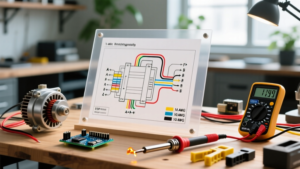
Before grabbing a screwdriver, you must understand the visual language of your specific schematic. While manufacturers vary, North American 240V hot tub wiring diagrams generally follow a standardized color code for the main terminal block:
- Red & Black (L1 & L2): The two 120V hot legs. Together, they provide 240V for the heater and high-speed pump. Individually, they provide 120V for lights, the blower, and the control board transformer.
- White (Neutral): The grounded conductor. Crucial for 120V components and providing the return path for the GFCI breaker's internal sensing toroid.
- Green or Bare Copper (Ground): The equipment grounding conductor (EGC). This must bond to the spa shell, heater tube, and pump wet ends.
On the low-voltage side of the diagram (usually 12V DC or 24V AC), you will see color-coded ribbon cables or specific pinouts for sensors. For instance, Balboa temperature sensors typically use a 2-pin or 3-pin plug, where the diagram will specify the expected resistance curve (e.g., 10kΩ at 77°F). If your diagram shows a separate heater contactor, look for the 240V coil trigger wires, often colored blue or yellow.
Step-by-Step GFCI Troubleshooting Flow
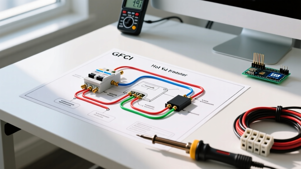
The most common reason homeowners search for a wiring diagram for a hot tub is to solve nuisance GFCI trips. A GFCI breaker (like the Eaton BR250GF or Siemens QF260A, which cost between $120 and $160 to replace) trips when it detects an imbalance of just 4 to 6 milliamps between L1/L2 and the Neutral wire, indicating current is leaking to ground.
Follow this systematic isolation procedure using your diagram to locate the terminal block identifiers (e.g., J1, J2, J3):
- Total Disconnect: With power OFF, use the diagram to locate the main terminal block where the spa's internal pigtails connect to the board. Disconnect all load wires (Heater, Pump 1, Pump 2, Blower, Ozone, Light) from the board and terminal blocks. Tape the ends to prevent accidental contact.
- The Bare Board Test: Turn the GFCI breaker ON. If it trips immediately, the fault lies in the main power cable, the terminal block itself (look for carbon tracking or melted plastic), or the control board's internal transformer. If it holds, proceed to step 3.
- Sequential Reconnection: Turn power OFF. Reconnect one component at a time, starting with the highest amperage loads (usually the heater). Turn power ON. If the breaker holds, turn power OFF and add the next component (e.g., Pump 1). The moment the breaker trips, you have identified the faulty circuit.
Component Isolation & Resistance Matrix
Once you have identified the suspect circuit via the sequential reconnection test, use your multimeter set to Ohms (Ω) to test the component. Consult the Fluke resistance testing guidelines to ensure your probes are zeroed. Compare your readings against the matrix below:
| Component (240V System) | Expected Resistance (Ohms) | Common Failure Mode | Diagram Check Point |
|---|---|---|---|
| 5.5 kW Heater Element | 10.4 Ω to 11.0 Ω | Internal short to copper tube (Ground Fault) | Heater Terminals 1 & 2 |
| 4.0 kW Heater Element | 14.4 Ω to 15.0 Ω | Dry-fire burnout (Open Circuit / OL) | Heater Terminals 1 & 2 |
| Ozone Generator (CD Corona) | High (Varies by model) | Internal moisture short to ground | Ozone J-Plug / Relay |
| 2-Speed Pump Motor | 10 Ω to 30 Ω (Windings) | Centrifugal switch failure or shorted windings | Common, High, Low Terminals |
| 120V Spa Light | Low (Incandescent) / High (LED) | Water intrusion in the light niche | Lighting Relay / Transformer |
Deep Dive: Testing the Heater Element for Ground Faults
If the diagram points to the heater circuit, testing resistance across the two element posts only tells you if the element is intact. To find the ground fault causing the GFCI trip, you must test for continuity between the element posts and the heater tube housing. Set your multimeter to the highest Ohms setting (or Megohms). Place one probe on a heater post and the other on the bare metal of the heater manifold. Any reading other than 'OL' (Open Loop/Infinite) indicates the element's internal magnesium oxide insulation has failed, allowing current to arc to the water. Replace the element immediately (typically an $85 to $110 part).
Diagnosing Contactors and Solid-State Relays
Many high-end hot tubs do not route 240V heater current directly through the main PCB. Instead, the wiring diagram will show a heavy-duty magnetic contactor. The PCB sends a low-voltage signal (usually 12V DC or 24V AC) to the contactor's coil (A1 and A2 terminals), which pulls in the mechanical contacts to power the heater.
If your GFCI holds, but the water remains cold, use the diagram to locate the coil terminals. With the spa calling for heat, measure the voltage across A1 and A2. If you read the correct control voltage but the contactor does not audibly 'click' and the heater terminals show 0V, the contactor coil is burned out. Conversely, if the contactor is stuck closed (welded contacts), the heater will run continuously, eventually causing a high-limit trip or boiling the water. According to the Consumer Product Safety Commission (CPSC), ensuring proper GFCI and thermal cutoff functionality is paramount to preventing spa-related electrical and thermal hazards.
Pump Motor Troubleshooting: Start vs. Run Windings
When troubleshooting a hum-and-stall condition on a 240V circulation or jet pump, the wiring diagram is essential for identifying the start and run windings. A standard 2-speed pump will have three main power wires: Common (C), Low Speed (L), and High Speed (H).
- Measure C to L: Should show the highest resistance (start/run winding in series).
- Measure C to H: Should show lower resistance (run winding only).
- Measure L to H: Should show the difference between the two.
If the motor hums but won't turn, the diagram will also point you to the external start capacitor (if equipped). A bulging or leaking capacitor is a dead giveaway, but you can also test it with a multimeter's capacitance setting. Always discharge the capacitor with a high-wattage resistor before testing to avoid destroying your meter's internal fuse.
Real-World Edge Case: The 'Phantom' Voltage Trip
Sometimes, the wiring diagram for a hot tub reveals a circuit that isn't failing electrically, but environmentally. A frequent edge case in 2026 involves the ozone generator's check-valve failing. Water backs up through the ozone tubing and pools inside the high-voltage corona discharge chamber. Because the ozone unit only runs during filter cycles, the GFCI trip seems random and intermittent. By tracing the ozone line on the physical plumbing and correlating it with the schematic's filter-cycle relay, you can isolate this hidden moisture fault without replacing expensive PCB boards.
Summary: The Schematic is Your Roadmap
Troubleshooting a 240V spa without a wiring diagram is like navigating a minefield blindfolded. By understanding the color codes, utilizing a systematic component isolation matrix, and verifying resistance values against manufacturer specifications, you can accurately pinpoint GFCI trips, heater failures, and pump faults. Always prioritize safety, respect the lethal nature of split-phase power, and let the schematic guide your multimeter probes to the exact point of failure.