
Decoding the Marathon Electric Motor Wiring Schematic
Marathon Electric, now operating under the Regal Rexnord umbrella, remains a dominant force in industrial, agricultural, and HVAC motor manufacturing. Whether you are commissioning a 1.5 HP single-phase agricultural pump motor or a 50 HP three-phase inverter-duty Blue Chip motor, interpreting the marathon electric motor wiring schematic correctly is the difference between a reliable installation and a catastrophic winding failure.
As of 2026, Regal Rexnord has consolidated much of Marathon's legacy documentation into their unified digital portal. While this streamlines access to CAD models and VFD integration guides, it often leaves field electricians searching for the raw, NEMA-standard terminal connection diagrams. This reference guide bridges that gap, providing exact terminal designations, voltage tap configurations, and torque specifications for the most common Marathon NEMA frame motors.
NEMA Standard Terminal Markings vs. IEC
Before making any terminations, identify whether your Marathon motor follows NEMA (National Electrical Manufacturers Association) or IEC (International Electrotechnical Commission) standards. Most domestic Marathon motors (e.g., Blue Chip, Black Max, and standard HVAC lines) utilize NEMA MG-1 terminal markings.
- NEMA Standard: Uses 'T' leads for power (T1, T2, T3, etc.) and 'P' leads for internal thermal protection (P1, P2).
- IEC Standard: Typically uses 'U', 'V', and 'W' designations (e.g., U1, V1, W1 for phase connections). IEC is more common on Marathon's specialized export or integrated gearmotor lines.
Critical Safety Warning: Always discharge the start and run capacitors using a 20,000-ohm, 5-watt bleeder resistor before touching any terminal block on a single-phase Marathon motor. Capacitors can retain lethal voltage for days if the centrifugal switch fails to close upon shutdown.
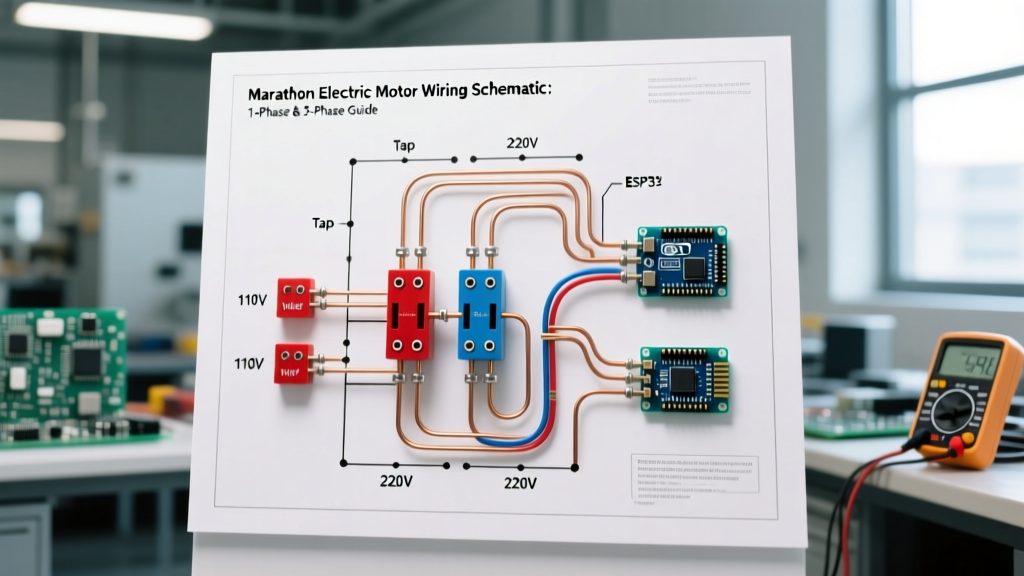
Single-Phase Dual Voltage (115/230V) Schematic Breakdown
The most frequently serviced Marathon motors in the field are 115/230V single-phase Capacitor-Start Induction-Run (CSIR) models, commonly found in 56 and 143T frames (e.g., Catalog #C145T34FC76). These motors typically feature six external T-leads: T1, T2, T3, T4, T5, and T8.
Voltage Tap Configurations
The schematic relies on reconfiguring the main (run) windings from parallel (115V) to series (230V), while the start winding and centrifugal switch remain in a fixed circuit.
| Voltage | Line 1 (Hot) Connections | Line 2 (Hot/Neutral) Connections | Internal Jumper / Tie |
|---|---|---|---|
| 115V (Low) | T1, T3, T8 | T2, T4, T5 | None |
| 230V (High) | T1, T8 | T2, T5 | T3 tied to T4 (Insulate) |
Note: Always verify the schematic printed on the inside of the motor's conduit box cover. Marathon occasionally updates internal winding layouts for specific high-efficiency (IE3/IE4) single-phase models, which may introduce T6 and T7 leads for auxiliary run capacitors.
Thermal Protection (P-Leads)
If your Marathon motor includes internal thermal overload protection, you will find two yellow wires labeled P1 and P2. These are not power leads. They connect to an internal bimetallic snap-disc thermostat embedded in the stator windings. To utilize them, wire P1 and P2 in series with your external motor contactor coil or PLC control circuit. When the stator reaches its critical temperature (typically 130°C to 155°C depending on the insulation class), the P-circuit opens, dropping out the contactor and preventing a winding fire.
Three-Phase 9-Lead (230/460V) Schematic Reference
For industrial applications, the Marathon Blue Chip line (e.g., 5 HP, 184T frame) utilizes a 9-lead dual-voltage configuration. Most modern Marathon three-phase motors are internally wired in a Wye (Star) configuration to reduce starting inrush current compared to Delta.
Wye (Star) 9-Lead Connections
| Voltage | Phase A (L1) | Phase B (L2) | Phase C (L3) | Neutral / Jumper Ties |
|---|---|---|---|---|
| 230V (Low) | T1, T7 | T2, T8 | T3, T9 | Tie T4, T5, T6 together |
| 460V (High) | T1 | T2 | T3 | T4-T7, T5-T8, T6-T9 |
When wiring for 460V, you are placing the two internal coils of each phase in series. It is imperative that you maintain the correct phase sequence (A-B-C) and do not cross-tie the phase pairs (e.g., tying T4 to T8), which will result in an immediate dead short and trip the upstream breaker instantaneously.
Common Wiring Failure Modes & Troubleshooting
Even experienced electricians make errors when interpreting the marathon electric motor wiring schematic under poor lighting or time pressure. Here are the most common field failures and how to diagnose them:
1. The 230V/115V Tap Trap (Start Winding Burnout)
The Error: The motor nameplate is set to 115V, but the supply voltage is 230V.
The Result: The main run windings are placed in parallel but receive double their rated voltage. The magnetic core saturates, drawing massive current. More critically, the start winding and capacitor circuit receive 230V instead of 115V. The centrifugal switch may fail to open due to excessive torque, or the start capacitor will vent/explode within seconds.
The Fix: Always measure the supply voltage at the disconnect switch before configuring the motor terminal block taps.
2. Loose Neutral on 230V Single-Phase
The Error: In a 230V single-phase setup, T3 and T4 are tied together but the connection is loose or relies on a damaged wire nut instead of a proper crimp or terminal block jumper.
The Result: The motor will hum violently, fail to start, and draw locked-rotor current (LRA) until the thermal overload trips. If the motor lacks thermal protection, the run winding will overheat and short to ground.
The Fix: Use a properly sized, insulated ring terminal to jumper T3 and T4 directly on the terminal block stud, rather than pig-tailing them in the conduit box.
Torque Specifications & Wire Gauge Sizing
Proper termination is just as critical as the schematic itself. Vibration from motor operation will loosen undertorqued connections, leading to arcing and terminal block melting.
Terminal Block Torque Values
- #14 to #10 AWG: 12 to 15 in-lbs
- #8 to #6 AWG: 25 to 30 in-lbs
- #4 to #2 AWG: 45 to 50 in-lbs
Always use a calibrated inch-pound torque screwdriver. Do not guess using a standard nut driver.
Conductor Sizing per NEC Standards
According to the NFPA 70 (National Electrical Code), motor branch circuit conductors must be sized at 125% of the motor's Full Load Amps (FLA) as listed on the nameplate, not the standard NEC tables. Furthermore, adherence to the NEMA MG-1 Motors and Generators Standard ensures compatibility with across-the-line starters.
| Motor Rating | Voltage | Nameplate FLA | 125% Calculation | Minimum AWG Size |
|---|---|---|---|---|
| 1.5 HP 1-Ph | 230V | 10.0A | 12.5A | #14 AWG |
| 5.0 HP 3-Ph | 460V | 7.6A | 9.5A | #14 AWG |
| 5.0 HP 1-Ph | 230V | 28.0A | 35.0A | #8 AWG |
Final Commissioning Checklist
- Verify Supply Voltage: Use a True-RMS multimeter to confirm L1-L2 voltage matches the selected nameplate tap within 10%.
- Check Rotation: For 3-phase Marathon motors, bump the starter to verify shaft rotation matches the driven equipment requirement. Swap any two phase leads (e.g., T1 and T2) to reverse rotation.
- Measure Amp Draw: Use a clamp meter on each phase under loaded conditions. The current should not exceed the nameplate Service Factor Amps (SFA). For a 1.15 SF motor, the maximum allowable continuous current is the FLA multiplied by 1.15.
- Secure Conduit Box: Ensure the conduit box lid gasket is seated properly to maintain the motor's IP55 or NEMA 12 ingress protection rating, preventing moisture from corroding the terminal block over time.
By strictly adhering to the marathon electric motor wiring schematic and applying these precision termination practices, you ensure maximum efficiency, thermal stability, and operational lifespan for your Regal Rexnord equipment.