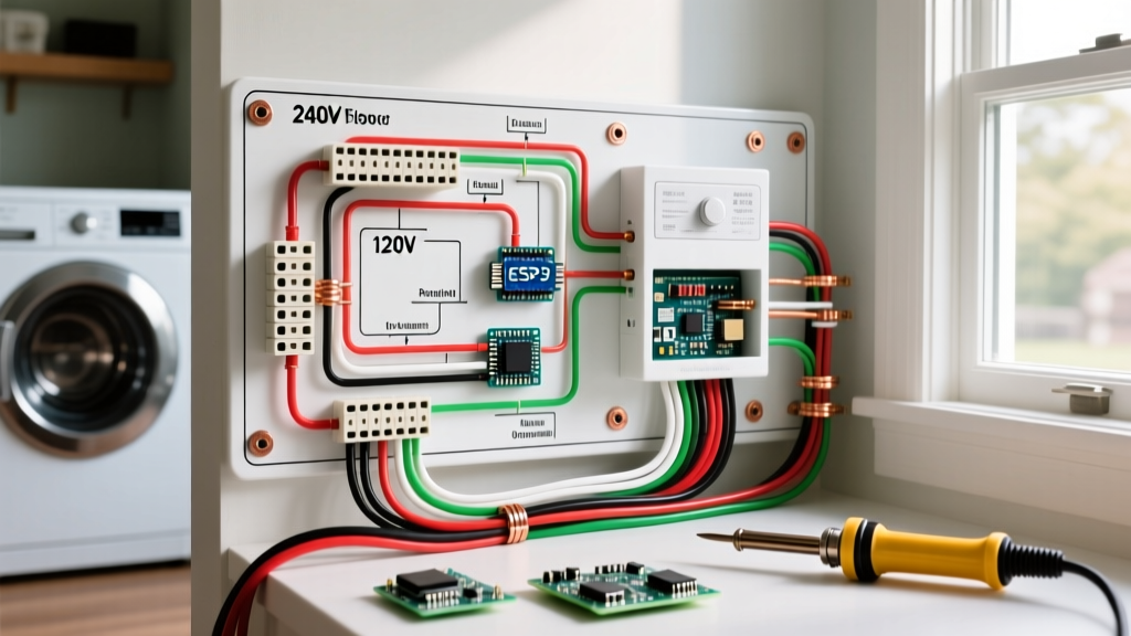

When homeowners and DIY enthusiasts attempt appliance repairs, finding an electrical wiring diagram simple enough to interpret is often the biggest hurdle. Factory schematics included in appliance tech sheets frequently resemble a chaotic maze of lines, switches, and relays. However, translating these complex blueprints into an electrical wiring diagram simple enough for field troubleshooting is a core skill that saves hundreds of dollars in service call fees. This guide breaks down the fundamental symbols, real-world appliance applications, and National Electrical Code (NEC) requirements you need to safely wire and troubleshoot major home appliances in 2026.
Decoding the Basics of an Electrical Wiring Diagram
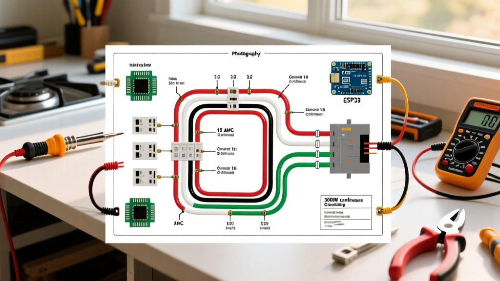
Before touching a wire stripper, you must understand the universal language of appliance schematics. Most manufacturers use standard NEMA (National Electrical Manufacturers Association) and IEC symbols. While a full schematic shows the entire control board logic, an electrical wiring diagram simple representation isolates the high-voltage power delivery from the low-voltage control circuits.
Critical Symbols to Memorize
- Normally Open (NO) Switch: Represented by two parallel lines with a gap and a hinged lever. Current cannot flow until the switch is actuated (e.g., a dryer door switch).
- Normally Closed (NC) Switch: The lever crosses the parallel lines, indicating current flows freely until the switch is triggered (e.g., a thermal fuse or high-limit thermostat).
- Capacitor: Shown as two parallel plates (one straight, one curved for polarized). Crucial for HVAC blower motors and compressor start circuits.
- Motor Windings: Typically drawn as overlapping loops or circles labeled 'C' (Common), 'S' (Start), and 'R' (Run).
According to the National Fire Protection Association (NFPA), misinterpreting wiring diagrams and bypassing safety switches like NC thermal fuses is a leading cause of residential electrical fires. Always verify the circuit is de-energized before testing continuity.
Real-World Application: 240V Electric Dryer Wiring
Let us apply an electrical wiring diagram simple framework to one of the most common DIY tasks: wiring a 240V electric dryer, such as the popular Whirlpool WED4815EW. Electric dryers require a split-phase 240V supply to power the heating element, alongside a 120V leg for the timer, motor, and control board.
Step-by-Step Terminal Block Connection
Modern NEC standards mandate a 4-prong NEMA 14-30R receptacle, separating the neutral and ground paths. If you are upgrading from an older 3-prong setup, the wiring diagram on the dryer's access panel will show you how to isolate the neutral bonding strap.
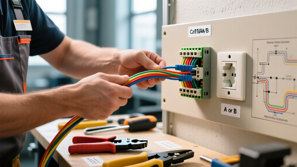
- Prepare the Cable: Strip 2 inches of the outer jacket from your 10/3 NM-B (Romex) cable. Strip exactly 1/2 inch of insulation from the four individual 10 AWG copper conductors.
- Ground (Green/Bare): Attach to the green grounding screw on the dryer chassis. Torque to 12-15 in-lbs.
- Neutral (White): Connect to the center silver terminal on the terminal block. Critical: Ensure the copper bonding strap is removed or folded back so it does not touch the center terminal.
- Hot Legs (Black and Red): Connect to the outer brass terminals (L1 and L2). The polarity between L1 and L2 does not matter for standard resistive heating elements.
120V Appliance Focus: Dishwasher Hardwire vs. Receptacle
Dishwashers, like the Bosch 800 Series (SHPM88Z75N), typically operate on a standard 120V, 15A or 20A circuit. The electrical wiring diagram simple layout for a dishwasher usually involves a basic junction box connection rather than a complex terminal block.
Under recent NEC updates (Article 210.8(D)), kitchen dishwashers require GFCI protection. Whether you hardwire the unit using a 14/2 or 12/2 NM-B cable into a junction box (like the Bosch SMZPCJB1UC kit) or use a 3-prong pigtail cord into a GFCI-protected receptacle, the internal wiring remains straightforward: Black to Brass (Hot), White to Silver (Neutral), and Bare/Green to the Green grounding screw.
Wire Gauge and Breaker Sizing Matrix
Selecting the correct wire gauge and breaker size is non-negotiable for safety and code compliance. Refer to the table below for standard appliance configurations:
| Appliance Type | Voltage | Max Amperage | Min. Copper Wire Gauge | Breaker Size | NEMA Receptacle |
|---|---|---|---|---|---|
| Electric Dryer | 240V | 30A | 10 AWG | 30A (2-Pole) | 14-30R |
| Electric Range/Oven | 240V | 40A - 50A | 8 AWG (40A) / 6 AWG (50A) | 40A or 50A (2-Pole) | 14-50R |
| Dishwasher (Hardwire) | 120V | 12A - 15A | 14 AWG (12 AWG preferred) | 15A or 20A (GFCI) | N/A (Hardwired) |
| Garbage Disposal | 120V | 8A - 10A | 14 AWG | 15A or 20A | 5-15R |
| HVAC Condenser | 240V | 20A - 30A | 12 AWG (20A) / 10 AWG (30A) | 20A or 30A (2-Pole) | Disconnect Box |
Troubleshooting with a Multimeter: Edge Cases and Failure Modes
An electrical wiring diagram simple guide is only useful if you know how to test the components it represents. The Consumer Product Safety Commission (CPSC) emphasizes that improper testing of high-voltage appliance components leads to severe shock hazards. Always use a Category III (CAT III) or Category IV (CAT IV) rated digital multimeter.
Testing a Dryer Heating Element
If your Whirlpool dryer spins but produces no heat, the wiring diagram will lead you to the heating element assembly. Unplug the dryer, disconnect the two wires leading to the element, and set your multimeter to Ohms (Ω).
- Normal Reading: 8 to 15 Ω. This indicates the internal nichrome wire is intact.
- Open Circuit (OL): The element is broken and must be replaced.
- Short to Ground: Place one probe on a terminal and the other on the metal casing. If you read anything other than 'OL', the element is shorted to the chassis, which will instantly trip your 30A breaker upon startup.
Testing Start Capacitors (HVAC and Appliances)
For appliances with induction motors (like HVAC blowers or large air compressors), the start capacitor provides the initial phase-shifted torque. A failed capacitor is the most common reason a motor hums but fails to spin. Disconnect the capacitor, safely discharge it with a 20,000-ohm 5-watt resistor, and use the capacitance setting (MFD/µF) on your multimeter. A 5 MFD 370VAC capacitor should read within 6% of its rated value (4.7 to 5.3 MFD). If it reads significantly lower, or shows a bulging casing, replace it immediately.
Frequently Asked Questions (FAQ)
Can I use a 3-prong cord on a new 4-prong dryer?
No. The NEC phased out 3-prong dryer receptacles (NEMA 10-30R) in the late 1990s because they combined the neutral and ground paths. If your home has an old 3-prong outlet, you must hire a licensed electrician to upgrade the circuit to a 4-wire setup with a NEMA 14-30R receptacle. Adapters are illegal and highly dangerous.
Where do I find the electrical wiring diagram for my specific appliance?
Most manufacturers hide the tech sheet inside the appliance. For dryers, it is usually tucked inside the lower kick-panel or taped to the back of the front access door. For dishwashers, check the underside of the unit near the junction box or inside the door panel. You can also search the exact model number on sites like Repair Clinic or Appliance Parts Pros to download the PDF schematic.
What does 'L1' and 'L2' mean on a 240V wiring diagram?
L1 and L2 represent Line 1 and Line 2, the two 120V 'hot' legs coming from your main electrical panel. In a split-phase residential system, these two legs are 180 degrees out of phase, providing 240V across them. On an electrical wiring diagram simple layout, L1 and L2 feed the main high-wattage loads, while the Neutral wire provides the 120V return path for timers and lights.
Final Safety Considerations
Working with appliance wiring requires strict adherence to safety protocols. According to NEMA standards, ensuring proper grounding and using correctly rated wiring devices prevents catastrophic equipment failure. Always turn off the main breaker, verify zero voltage with a non-contact voltage tester and a multimeter, and never bypass thermal fuses or high-limit thermostats. By mastering how to read an electrical wiring diagram simple enough for practical application, you empower yourself to diagnose, repair, and safely maintain your home's most critical machines.