
The Critical Intersection of Towing Safety and Electrical Code
Wiring a trailer electric brake controller is not merely a convenience upgrade; it is a critical safety system governed by strict federal and industry standards. A flawed trailer electric brake controller wiring diagram implementation doesn't just result in poor stopping power—it leads to melted harnesses, trailer fires, and catastrophic detachment on highways. Whether you are wiring a 7,000 lb travel trailer or a 14,000 lb equipment hauler, adherence to the National Fire Protection Association (NFPA) and Federal Motor Carrier Safety Administration (FMCSA) codes is non-negotiable.
This guide provides a deep-dive, code-compliant wiring blueprint for proportional brake controllers (such as the Tekonsha Prodigy P3 or Redarc Tow-Pro Elite), focusing on exact wire gauges, overcurrent protection, and mandatory fail-safe circuits.
Anatomy of a Code-Compliant Brake Circuit
Before cutting or crimping a single wire, you must understand the standardized 7-way RV blade connector (per RVIA and SAE J286 standards). The brake circuit relies on specific pins, and crossing them is a leading cause of electrical fires.
- Pin 1 (White): Dedicated Chassis Ground (Must be 10 AWG minimum)
- Pin 2 (Blue): Electric Brake Output Feed
- Pin 3 (Green): Tail and Running Lights
- Pin 4 (Black): 12V Auxiliary Power (Used for breakaway switch and interior charging)
- Pin 5 (Yellow): Left Turn/Stop
- Pin 6 (Brown): Right Turn/Stop
- Pin 7 (Purple): Reverse Lights / Auxiliary
CRITICAL SAFETY WARNING: Never rely on the hitch ball or trailer coupler as the primary ground for your brake circuit. The NFPA 1192 standard explicitly requires a dedicated ground wire. Hitch grounding causes severe voltage drop, resulting in weak braking and potential back-feeding that can fry your tow vehicle's CAN-bus system.
Step-by-Step Tow Vehicle Wiring Flow
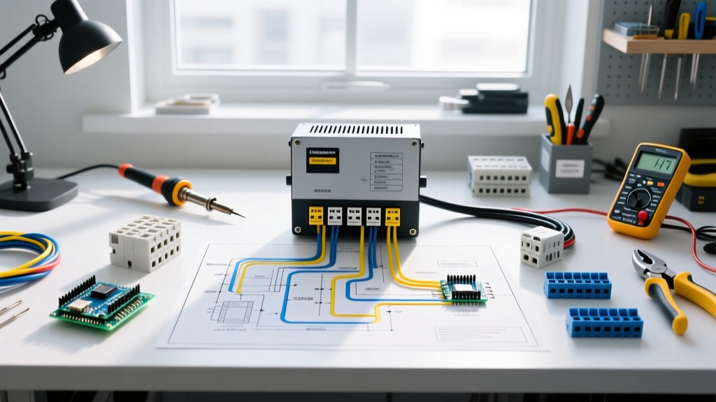
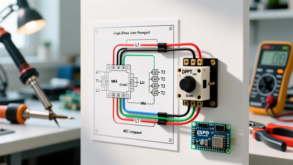
Proper installation in the tow vehicle requires routing from the battery to the controller, and then to the 7-way connector. Below is the exact sequence for a standard 4-wire proportional controller (e.g., Tekonsha P3 Model 90195).
1. Main Power Feed & Overcurrent Protection
Run a 10 AWG stranded copper wire from the positive terminal of the tow vehicle's battery to the brake controller's Black wire. You must install a 30-Amp Resettable Circuit Breaker (such as the Bussmann 1830 or 1840 series) within 6 inches of the battery positive terminal. This complies with NFPA 70 (NEC) Article 551 regarding overcurrent protection in mobile DC systems.
2. Controller Output to 7-Way Connector
Connect the controller's Blue output wire using 10 AWG wire directly to Pin 2 on the 7-way socket. Do not splice into existing trailer lighting harnesses. The blue wire must be routed inside a split-loom conduit to protect against road debris and exhaust heat, which can melt the insulation and cause a dead short to the chassis.
3. Brake Pedal Switch Signal
The Red wire connects to the vehicle's cold side of the brake light switch. On modern vehicles with multiplexed wiring or CAN-bus systems (common in 2020+ trucks), you must use a dedicated stoplight adapter harness (e.g., Tekonsha Plug-In 3063-P) rather than tapping the wire manually, preventing voided warranties and ECU damage.
Wire Gauge Selection & Voltage Drop Matrix
Electric brake magnets draw significant current. A dual-axle trailer (4 magnets) can draw up to 12-15 amps continuously under heavy braking. Undersized wiring causes voltage drop, meaning the brakes at the rear axle receive significantly less power than the front axle, leading to trailer sway and jackknifing.
| Wire Gauge (AWG) | Max Continuous Amps | Max Run Length (Keep <3% Drop at 15A) | Application |
|---|---|---|---|
| 14 AWG | 15 Amps | 8 Feet | Single axle internal jumper wires only |
| 12 AWG | 20 Amps | 15 Feet | Single axle trailers (2 magnets) |
| 10 AWG | 30 Amps | 25 Feet | Tow vehicle main feed & Dual-axle main trunk |
| 8 AWG | 40 Amps | 40+ Feet | Tri-axle heavy haulers (6 magnets) |
Mandatory Safety: The Breakaway Switch Circuit
Under 49 CFR § 393.43, any trailer with a Gross Vehicle Weight Rating (GVWR) over 3,000 lbs must be equipped with an automatic breakaway braking system. This system is entirely independent of the tow vehicle's brake controller.
How to Wire the Breakaway Switch
- Power Source: Run a 12 AWG wire from the trailer's dedicated 12V auxiliary battery (not the tow vehicle's feed) through a 15-Amp inline fuse.
- The Switch: Connect this fused power to one terminal of the breakaway switch (mounted near the trailer tongue).
- The Lanyard: The steel cable must be attached to the tow vehicle's frame or a dedicated loop, not the safety chains or the hitch receiver.
- Output: Connect the second terminal of the breakaway switch directly to the Blue brake feed wire on the trailer side of the junction box.
Operational Logic: If the trailer detaches, the lanyard pulls the pin from the switch. The trailer's onboard battery sends 12V directly to the brake magnets, locking the trailer wheels instantly, bypassing the tow vehicle entirely.
Expert Troubleshooting Matrix
Even with a perfect diagram, environmental factors and poor crimping can cause faults. Use this matrix to diagnose issues without guessing.
| Symptom / Controller Error | Root Cause & Failure Mode | Code-Compliant Fix |
|---|---|---|
| Controller displays "S.H." (Short Circuit) when manual override is pressed. | Blue output wire insulation has chafed against the trailer frame or hitch, grounding the circuit. | Inspect the entire blue wire run. Re-route away from moving suspension parts and enclose in heavy-duty split loom. |
| Trailer brakes lock up violently when tow vehicle headlights are turned on. | Grounding through the hitch ball. Pin 1 (Ground) and Pin 3 (Tail Lights) are sharing a return path, back-feeding 12V into the brake circuit. | Install a dedicated 10 AWG white ground wire from the 7-way plug directly to the trailer chassis using a star washer and bare metal contact. |
| Controller powers on, but reads "0.0" output even when braking hard. | Red stoplight wire is connected to the wrong circuit (e.g., cruise control cancel or 12V constant) or CAN-bus signal is uninterpreted. | Use a digital multimeter to verify the red wire only sees 12V when the brake pedal is physically depressed. Install a CAN-bus stoplight adapter if necessary. |
| Breakaway system fails to lock brakes during annual pull-test. | Trailer auxiliary battery is sulfated/dead, or the inline fuse is blown from a previous short. | Replace auxiliary battery. Test voltage at the breakaway switch terminals; must read >12.4V DC. Replace fuse with exact amperage rating. |
Final Compliance and Maintenance Directives
To maintain compliance with NFPA 1192 Standard on Recreational Vehicles and ensure long-term reliability, all wire connections must be made using adhesive-lined heat shrink crimps (e.g., 3M Highland or Ancor marine-grade). Standard butt connectors will wick moisture via capillary action, leading to green corrosion and high-resistance joints within six months.
Furthermore, dielectric grease must be applied to the 7-way connector pins to prevent oxidation, but never inside the actual crimp barrels. By treating your trailer electric brake controller wiring not just as an accessory, but as a life-saving, code-regulated system, you ensure maximum stopping power and legal compliance on every journey.