
Understanding the Electric Tankless Water Heater Wiring Diagram
Installing an electric tankless water heater is one of the most demanding electrical projects a homeowner or contractor can undertake. Unlike traditional tank heaters that draw a steady 18 to 25 amps, a whole-house electric tankless unit can pull anywhere from 80 to 150 amps at peak demand. Because of this massive electrical load, interpreting an electric tankless water heater wiring diagram correctly is not just a matter of code compliance—it is critical for fire prevention and system longevity.
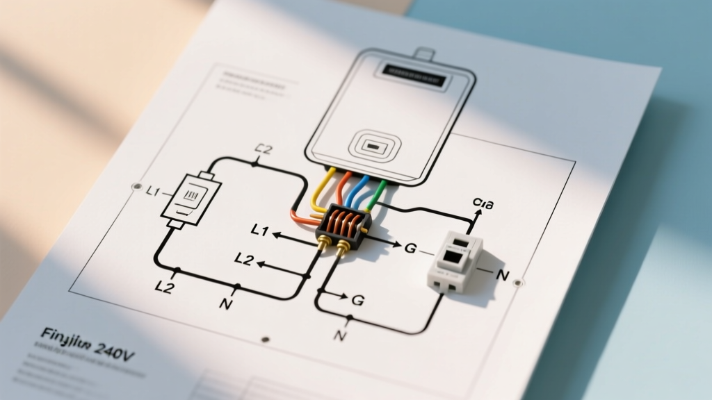
At its core, the wiring diagram for a 240-volt tankless unit is a pure resistive load circuit. However, modern smart units (like the Stiebel Eltron Tempra Plus series or Rheem RTEX Pro models) incorporate digital flow sensors and microprocessor control boards that require precise voltage delivery. A standard schematic will show two or three separate 240V circuit inputs, each protected by a dedicated double-pole breaker, feeding directly into internal terminal blocks. There is typically no neutral wire required for the heating elements themselves, though a ground wire is mandatory.
Critical Wire Gauge Sizing for Tankless Units (AWG Reference)
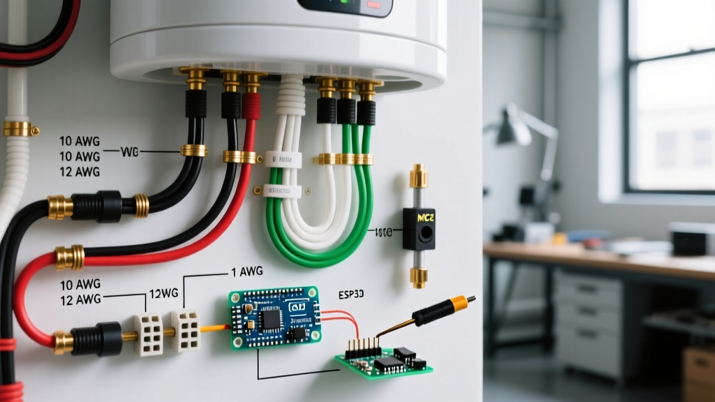
Selecting the correct American Wire Gauge (AWG) is the most common point of failure in DIY tankless installations. Undersized wires will overheat, melt insulation, and trip breakers continuously. According to the Cerrowire Ampacity Tables and National Electrical Code (NEC) Article 240.4, your wire gauge must match or exceed the breaker rating.
| Unit Size (kW) | Max Amperage (at 240V) | Required Breaker(s) | Minimum Copper Wire Gauge (NM-B) | Example Model |
|---|---|---|---|---|
| 3.5 kW - 5.5 kW | 15A - 23A | 1 x 30A Double-Pole | 10 AWG | EcoSmart ECO 11 |
| 8 kW - 12 kW | 33A - 50A | 1 x 50A or 60A Double-Pole | 6 AWG | Stiebel Eltron Tempra 12 |
| 18 kW - 24 kW | 75A - 100A | 2 x 40A or 2 x 50A Double-Pole | 8 AWG (per circuit) | Rheem RTEX-24 |
| 27 kW - 36 kW | 112A - 150A | 3 x 40A or 3 x 50A Double-Pole | 8 AWG or 6 AWG (per circuit) | EcoSmart ECO 27 / Tempra 36 |
NM-B Cable vs. THHN in Conduit
When reading your electric tankless water heater wiring diagram, note whether the manufacturer specifies NM-B (Romex) or individual THHN/THWN wires in conduit. A 6 AWG NM-B cable is rated for 55 amps. Under NEC 240.4(B), you are permitted to round up to the next standard breaker size, meaning a 6 AWG NM-B can legally be used on a 60-amp breaker. However, if you are pulling individual THHN wires through EMT conduit, 6 AWG THHN is rated for 65 amps (at 75°C column), providing a much safer thermal margin for continuous high-draw applications.
NEC Color Code Standards for 240V Appliances
Proper color coding ensures that future electricians and inspectors can safely service the unit. For a standard 240V, 2-wire plus ground tankless water heater circuit, the NEC mandates the following color scheme:
- Black Wire: Line 1 (Hot). Connects to one pole of the double-pole breaker and the L1 terminal on the heater.
- Red Wire (or White re-identified): Line 2 (Hot). Connects to the second pole of the breaker and the L2 terminal. If using a 2-wire NM-B cable that only contains Black, White, and Bare wires, NEC 200.7(C)(2) requires you to permanently re-identify the white wire as a hot conductor using black or red electrical tape or heat shrink at both the panel and the heater terminal block.
- Bare or Green Wire: Equipment Grounding Conductor (EGC). Must be terminated to the grounding bus bar in the panel and the green grounding screw on the heater chassis.
Expert Warning: Never use a white or gray wire as a hot conductor without permanent re-identification at every point where the cable is accessible. Inspectors will immediately fail an installation if an unmarked white wire is landed on a 240V breaker or a tankless L2 terminal block.
Step-by-Step Wiring Execution & Torque Specifications
Modern electrical codes have cracked down on loose connections, which are the primary cause of thermal runaway and melted terminal blocks in high-amperage appliances. Follow these execution steps to ensure a flawless installation:
- Strip the Insulation: Use a precision wire stripper to remove exactly 5/8-inch of insulation from the conductors. Stripping too little leaves exposed copper outside the terminal; stripping too much leaves bare wire exposed outside the block.
- Seat the Wires: Insert the Black and Red (or re-identified White) wires into the L1 and L2 terminal blocks. Ensure no stray copper strands are splaying outward, which could cause a dead short against the chassis.
- Apply Calibrated Torque: NEC 110.14(D) requires the use of a calibrated torque tool for circuits rated over 100 amps, but industry best practice dictates using a torque screwdriver for all tankless connections. Set your torque screwdriver to the manufacturer's specification (typically between 20 and 25 in-lbs for standard 6-8 AWG terminal blocks).
- Verify the Ground: Terminate the bare copper ground wire to the designated green grounding screw. Do not wrap the ground wire around the element mounting brackets.
Edge Cases: Voltage Drop and Aluminum Wiring
Managing Voltage Drop Over Long Runs
Tankless water heaters are highly sensitive to voltage drop. If the voltage at the terminal block drops below 228V (a 5% drop from 240V), the heating elements will underperform, and the internal relays may chatter or fail prematurely. The NEC recommends a maximum 3% voltage drop on branch circuits.
If your electrical panel is located more than 50 feet away from the water heater installation point, you must upsize your wire gauge by at least one step. For example, if your diagram calls for 8 AWG wire for a 40-amp circuit, you must upgrade to 6 AWG for a 75-foot run to maintain optimal voltage delivery.
Aluminum vs. Copper Terminations
While copper is the undisputed standard for interior appliance wiring, some older homes or budget installations attempt to use aluminum SER cable. If you must transition from aluminum feeder wires to the copper pigtails required by the tankless unit, you cannot simply twist them together with standard wire nuts. You must use AlumiConn lug connectors or a dual-rated (CU/AL) split bolt connector treated with Noalox anti-oxidant paste. Furthermore, verify that the tankless unit's internal terminal blocks are rated for aluminum; most European and Asian imports (like Eemax or Stiebel Eltron) are strictly rated for copper only.
Frequently Asked Questions
Do I need a neutral wire for my electric tankless water heater?
In 95% of residential installations, no. Pure 240V resistive heating elements only require two hot wires and a ground. However, some advanced hybrid models or units with 120V internal recirculation pumps may require a 4-wire setup (Hot, Hot, Neutral, Ground). Always consult the specific schematic on the inside of your unit's access panel.
Can I use a 50-amp breaker with 6 AWG wire for a 48-amp continuous draw?
No. Under NEC Article 210.20(A), continuous loads (those expected to run for 3 hours or more) require the branch circuit to be rated at 125% of the continuous load. While a tankless heater rarely runs for 3 hours straight, inspectors often classify high-demand water heating as a continuous load to be safe. A 48-amp draw requires a minimum 60-amp breaker and 4 AWG copper wire (if using NM-B).
Why does my breaker trip immediately when the hot water is turned on?
Immediate tripping usually indicates a dead short or a severe wiring error, such as landing a hot wire on the ground bus, or a failed internal heating element. Use a multimeter to check the resistance (Ohms) across the L1 and L2 terminals with the power off. A healthy element should read between 10 and 20 Ohms. A reading of 0 Ohms indicates a shorted element.
Final Safety and Code Compliance Notes
Before energizing your newly wired electric tankless water heater, ensure your main service panel has the capacity to handle the added load. A 27kW unit adds over 112 amps to your home's electrical demand. According to the U.S. Department of Energy, upgrading to a high-capacity tankless system often necessitates a main panel upgrade from 100A to 200A or even 300A. Always refer to the latest National Fire Protection Association (NFPA) NEC guidelines and pull the required local permits before beginning any high-amperage electrical work.