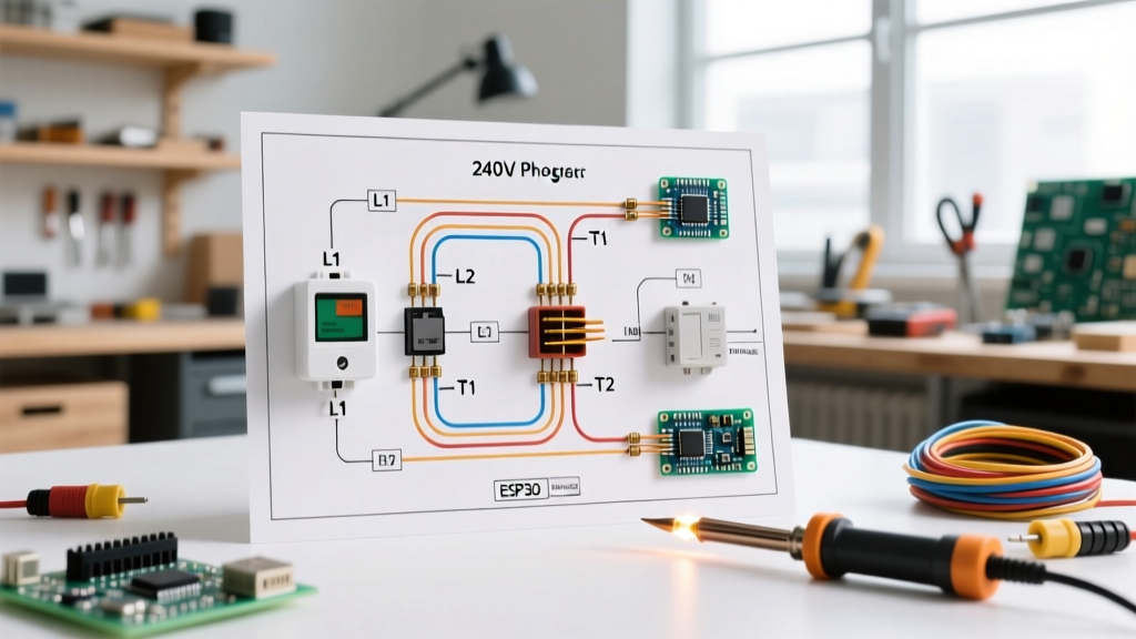

Decoding the 240v Electric Heater Wiring Diagram with Thermostat
When a 240V electric baseboard or wall heater fails in the dead of winter, the difference between a quick fix and an expensive service call lies in your ability to read a schematic. Unlike low-voltage HVAC systems that rely on complex control boards and 24V transformers, pure resistive 240V heating circuits are brutally simple. However, their simplicity masks the severe shock hazard and specific National Electrical Code (NEC) requirements governing them. In this guide, we will use the standard 240v electric heater wiring diagram with thermostat as a diagnostic map to isolate failures, test components, and safely restore heat to models like the Cadet F-Series, King H-Series, and Marley Q-Series.
⚠️ CRITICAL SAFETY WARNING: 240V circuits carry lethal current. Always perform Lockout/Tagout (LOTO) procedures at the main panel before opening any junction box, adhering to OSHA hazardous energy standards. When testing live voltage, you must use a CAT III 600V or CAT IV 600V rated digital multimeter (DMM). Never use cheap, unrated automotive testers on mains voltage.Anatomy of a Line-Voltage Thermostat Circuit
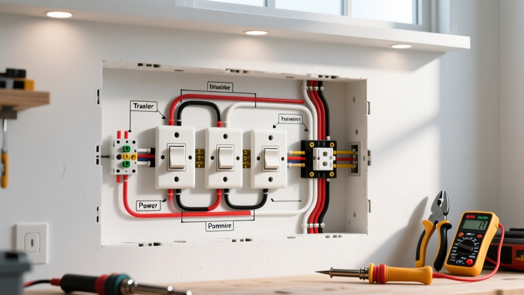
Before troubleshooting, you must understand the four primary terminals on a standard double-pole line-voltage thermostat (such as the Honeywell CT410B or Cadet K523):
- L1 & L2 (Line): These connect to the incoming 240V power from the double-pole breaker. L1 carries 120V to ground, and L2 carries 120V to ground, yielding 240V across them.
- T1 & T2 (Load): These connect to the heater element. When the thermostat calls for heat, the internal bimetallic switch closes, allowing 240V to pass from L1/T1 and L2/T2 to the resistive element.
- Ground (Bare/Green): Bypasses the thermostat entirely. It connects directly from the panel's ground bar to the heater's metal chassis and junction box.
Expert Note: Pure 240V resistive heaters do not use a neutral wire (white). If you see a white wire in a 240V heater junction box, it is being used as a hot conductor and must be re-identified with black or red electrical tape per NEC Article 200.7.
Step-by-Step Fault-Finding Using the Diagram
Symptom 1: Heater is Completely Dead (No Heat, No Fan)
This is the most common complaint. The thermostat is set to maximum, but the unit remains cold. Follow the diagram from the source to the load:
- Verify Breaker Voltage: Set your DMM to AC Voltage. Place probes on the two breaker terminals. You should read between 230V and 245V. If you read 0V, the breaker is tripped or the panel bus bar is damaged. If you read 120V across the two poles, one leg of the double-pole breaker has failed internally.
- Test Thermostat Line Side (L1/L2): With the thermostat removed (but wires safely separated and live), test across L1 and L2. If 240V is present here but the heater is dead, the fault is downstream.
- Test Thermostat Load Side (T1/T2): Turn the thermostat dial to the highest setting. Test across T1 and T2. If you have 240V here, the thermostat is passing current correctly. The fault is in the heater element or the wiring between the thermostat and the heater.
- Test Element Continuity: Kill the power at the breaker. Disconnect the heater element wires. Set your DMM to Ohms (Ω) and touch the probes to the element terminals. A reading of 'OL' (Open Loop) or infinite resistance means the element is burnt out and must be replaced.
Symptom 2: Heater Runs Continuously (Thermostat Won't Cut Off)
If the room is sweltering but the heater refuses to shut off, the thermostat has likely failed in the 'closed' position. Over time, the high inrush current of a cold heating element can cause micro-arcing inside the thermostat. This arcing generates intense localized heat, eventually welding the internal bimetallic contacts together. The only fix is to replace the thermostat. Do not attempt to pry the contacts apart; the structural integrity of the switch is compromised.
Symptom 3: Breaker Trips Instantly Upon Reset
An instantaneous trip indicates a dead short. According to U.S. Department of Energy guidelines on electric resistance heating, elements can degrade and rupture, causing the internal nichrome wire to touch the grounded metal sheath. To confirm, kill power, disconnect the element, and set your DMM to continuity or resistance. Place one probe on the element terminal and the other on the bare metal casing of the heater. Any reading below infinite resistance confirms a ground fault. Replace the element immediately.
Multimeter Diagnostic Matrix: Expected Element Resistance
When testing continuity, knowing the exact expected resistance of your heating element separates amateurs from professionals. Use Ohm's Law (R = V² / P) to determine if an element is partially degraded. Assuming a nominal 240V supply, refer to the table below:
| Heater Wattage (W) | Amperage Draw (A) | Expected Resistance (Ω) | Required Breaker / Wire |
|---|---|---|---|
| 1000W | 4.16A | 57.6 Ω | 15A / 14 AWG (Min) |
| 1500W | 6.25A | 38.4 Ω | 20A / 12 AWG |
| 2000W | 8.33A | 28.8 Ω | 20A / 12 AWG |
| 2500W | 10.41A | 23.0 Ω | 20A / 12 AWG |
| 3000W | 12.50A | 19.2 Ω | 30A / 10 AWG |
Diagnostic Tip: If your 1500W element reads 25 Ω instead of 38.4 Ω, it has developed an internal short between the coils, drawing excessive current and creating a severe fire hazard. Replace it regardless of whether it still produces heat.
2026 Smart Thermostat Upgrade Considerations
Many homeowners troubleshooting older mechanical thermostats decide to upgrade to Wi-Fi-enabled smart thermostats for better energy management. However, retrofitting a smart thermostat into a legacy 240v electric heater wiring diagram with thermostat setup presents unique challenges in 2026.
The Neutral Wire Dilemma: Smart thermostats like the Sinopé TH1123WF (approx. $180) or the Mysa Smart Thermostat for Baseboard (approx. $149) require continuous power to run their internal Wi-Fi radios and OLED displays. Legacy 2-wire 240V setups lack a neutral wire. While some modern units use a 'phantom neutral' (leaking a tiny current through the heating element to complete the circuit), this can cause high-resistance elements to faintly glow or 'ghost heat' when the thermostat is supposed to be off. Always verify the manufacturer's minimum wattage requirements before installing a 2-wire smart thermostat.
If your smart thermostat requires a dedicated neutral, you must pull a new 12/3 or 10/3 NM-B (Romex) cable from the panel to provide the 120V line, 120V line, neutral, and ground required for the smart control head. Never attempt to use the bare ground wire as a neutral return; this will trip a GFCI/AFCI breaker immediately and violates NEC Article 250.
Final Verification and Code Compliance
After replacing a faulty element, thermostat, or repairing a wiring fault, perform a final operational test. Turn the thermostat to its lowest setting, re-energize the breaker, and slowly increase the temperature until you hear the mechanical 'click' of the relay or bimetallic strip. Verify that the heater element begins to radiate heat within 60 seconds. Ensure all wire nuts are secured with electrical tape and that the junction box cover plate is firmly attached to contain any potential arc flashes. By methodically following the 240v electric heater wiring diagram with thermostat, you ensure safe, code-compliant, and reliable heat for years to come.