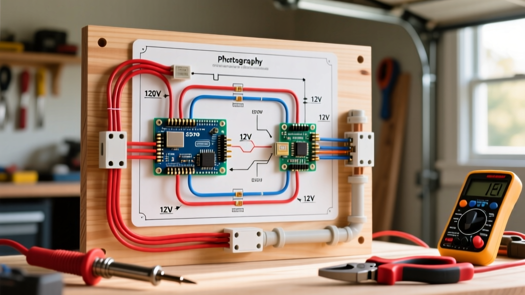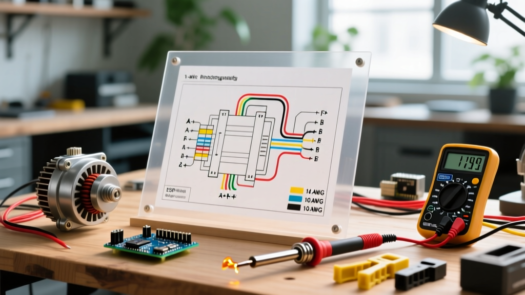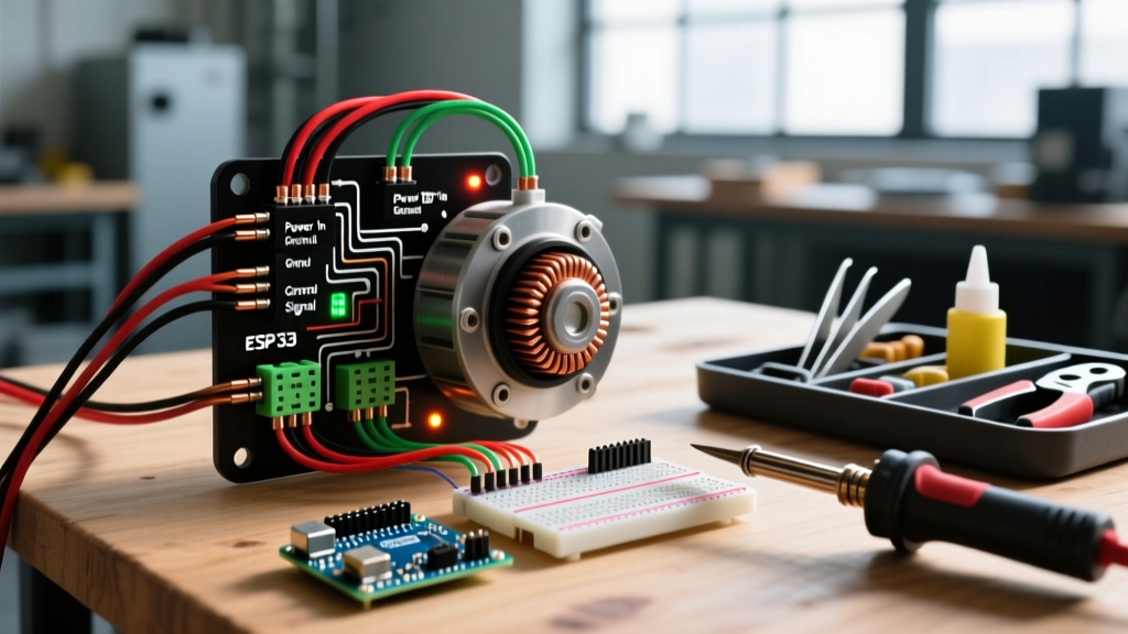

When an electric Power Take-Off (PTO) clutch fails on a commercial zero-turn mower or agricultural tractor, the immediate assumption is often a burnt-out electromagnetic coil. However, in over 70% of field failures, the root cause traces back to an improperly executed wiring harness. Understanding and correctly implementing an electric PTO clutch wiring diagram is critical for ensuring reliable blade engagement, preventing melted dashboard switches, and extending the operational lifespan of the clutch assembly.
This comprehensive, step-by-step walkthrough dissects the anatomy of a heavy-duty 12V DC PTO clutch circuit. We will cover exact wire gauges, relay configurations, flyback diode integration, and the 2026 industry shift toward Pulse Width Modulation (PWM) solid-state controllers.
The Physics of Engagement: Why Direct Wiring Fails
A common and catastrophic mistake in DIY mower repair is wiring the PTO clutch directly through the dashboard engagement switch. While a typical Ogura or Warner Electric PTO clutch might only draw 2.5 to 3.5 amps of continuous holding current, the inrush current required to initially magnetize the coil and pull the armature across the air gap can spike to 10 or 12 amps for several hundred milliseconds.
Routing a 12-amp inrush spike through a standard 5-amp dashboard toggle switch will rapidly cause internal arcing, melting the plastic housing and fusing the contacts. A proper electric PTO clutch wiring diagram isolates the high-amperage load circuit from the low-amperage control circuit using an automotive-grade relay or a solid-state PWM controller.
Component Sizing & Material Specifications
Before cutting a single length of wire, verify your materials against the specifications below. Using undersized wire or incorrect terminals is the primary cause of voltage drop, which leads to clutch slippage and premature friction surface wear.
| Component | Specification / Rating | Engineering Rationale |
|---|---|---|
| Main Power Wire | 12 AWG TXL (High-Temp) | Handles 12A inrush without voltage drop; TXL insulation resists engine bay heat. |
| Control Circuit Wire | 14 AWG or 16 AWG | Sufficient for the < 1A trigger current required by the relay coil. |
| Inline Fuse | 20A ATO Blade Fuse | Protects against dead shorts while allowing for initial inrush current spikes. |
| Switching Relay | 40A Bosch-Style (4-Pin) | Standard 30A relays degrade under repeated inductive kickback; 40A provides a safety margin. |
| Terminals | Ring Terminals (12-10 AWG) | Spade terminals vibrate loose on clutch blades; ring terminals ensure permanent mechanical connection. |
| Flyback Diode | 1N5408 (3A, 1000V) | Dissipates inductive voltage spikes when the clutch is disengaged, saving the relay contacts. |
Step-by-Step Electric PTO Clutch Wiring Diagram Walkthrough
Follow this exact sequence to build a robust, fail-safe PTO clutch circuit. This configuration applies to most 12V DC electromagnetic clutches, including the Warner Electric 5000 Series and equivalent aftermarket models.
Step 1: Main Power Feed and Fusing
Begin at the positive terminal of the battery or the main starter solenoid post. Cut a length of 12 AWG red TXL wire long enough to reach your relay mounting location. Crimp a 3/8-inch ring terminal on the battery end and secure it with a star washer to ensure a bite into the metal. Crucial: Install a 20A ATO inline fuse holder within 6 inches of the battery connection point. This ensures that if the main power wire chafes against the mower frame, the circuit is dead before it can start a fire.
Step 2: The Control Circuit and Relay Trigger
The control circuit originates at the ignition switch (to ensure the clutch cannot be engaged if the key is off). Run a 14 AWG wire from an ignition-hot source to one terminal of your dashboard PTO toggle switch. Run a second 14 AWG wire from the output side of the toggle switch to Pin 86 (the positive trigger coil pin) on your 4-pin relay. Connect Pin 85 (the negative coil pin) directly to a clean chassis ground. When the operator flips the dash switch, it sends a low-amp signal to energize the relay's internal electromagnet.
Step 3: Load Side Routing and Flyback Diode Integration
Connect the fused main power wire to Pin 30 (the common input) on the relay. Next, run a heavy-duty 12 AWG wire from Pin 87 (the normally open output) directly to the positive blade terminal on the PTO clutch.
The Flyback Diode Integration: Because a clutch coil is a massive inductor, suddenly cutting power to it causes the collapsing magnetic field to generate a reverse voltage spike (often exceeding 100V). This spike will pit and weld your relay contacts over time. To prevent this, solder a 1N5408 flyback diode across the clutch terminals. The silver band on the diode must point toward the positive wire. This creates a closed loop for the inductive spike to safely dissipate as heat within the coil.
Step 4: Establishing a Zero-Resistance Ground
Do not rely on the clutch mounting bolts to ground the clutch assembly; paint, rust, and engine vibration will compromise the connection. Run a dedicated 12 AWG black ground wire from the negative blade terminal on the clutch directly to the engine block or the negative battery post. Use a heavy-duty ring terminal and a star washer to bite through the paint down to bare metal. Apply a dab of dielectric grease over the crimped barrel (not the contact surface) to prevent galvanic corrosion.
Advanced 2026 Upgrade: PWM Solid-State Controllers
While the traditional relay-based electric PTO clutch wiring diagram remains the standard for residential equipment, the commercial landscaping industry in 2026 has largely transitioned to Pulse Width Modulation (PWM) solid-state controllers.
Expert Insight: A PWM controller initially applies full 12V to the clutch to achieve rapid engagement, then rapidly pulses the voltage down to an 8V to 9V holding state. This reduces the continuous heat generated inside the coil by up to 40%, drastically extending the life of the clutch bearings and friction linings on high-cycle commercial mowers.
Wiring a PWM controller eliminates the need for a mechanical relay and a flyback diode, as the solid-state MOSFETs handle the inductive kickback internally. You simply wire the heavy 12 AWG power and ground through the controller's main terminals, and connect the clutch leads to the output terminals.
Critical Troubleshooting: Voltage Drop vs. Air Gap
If your newly wired PTO clutch is slipping, failing to engage, or overheating, you must isolate whether the issue is electrical or mechanical. Use a digital multimeter to perform a live voltage drop test.
- The Voltage Drop Test: Set your multimeter to DC Volts. Place the red probe on the battery positive post and the black probe on the positive blade terminal of the clutch while the PTO is engaged. A reading above 0.2V indicates excessive resistance in the wiring, usually caused by a loose crimp, corroded fuse holder, or undersized wire. Repeat the test on the ground side (black probe to battery negative, red probe to clutch negative).
- The Air Gap Calibration: If the voltage at the clutch reads a solid 11.5V or higher but the clutch still slips or clicks without engaging, the mechanical air gap has worn out of specification. Using a brass feeler gauge, measure the gap between the armature and the rotor. Most Warner and Ogura clutches require a precise gap of 0.015 to 0.020 inches. If the gap exceeds 0.025 inches, the magnetic field cannot physically pull the armature across the void. Adjust the gap using the factory adjustment nuts or replace the clutch assembly if the friction surfaces are worn past the service limit.
Expert Safety & Maintenance Directives
Always disconnect the negative battery terminal before stripping, crimping, or routing wires near the engine block. When routing the 12 AWG clutch harness, maintain a minimum clearance of 4 inches from the exhaust manifold and utilize split-loom tubing secured with UV-resistant zip ties. Finally, inspect the clutch wiring connector boots annually; water ingress into the spade or blade connectors will cause electrolysis, leading to a green, powdery corrosion that silently increases circuit resistance and mimics a failing clutch coil.