
Understanding the Blueprint of Your Home's Power
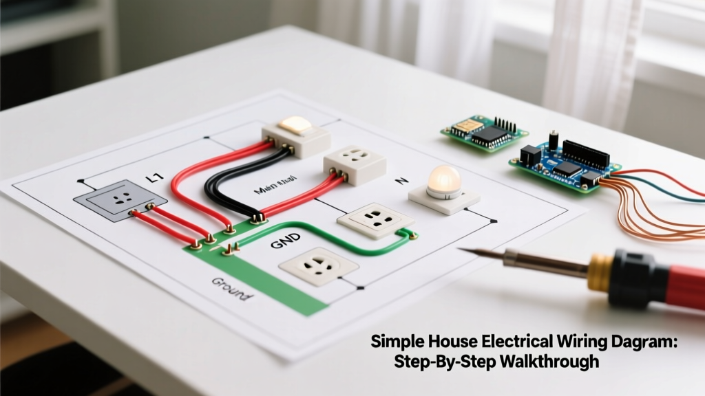
When tackling a residential renovation or new addition, interpreting a simple house electrical wiring diagram is the critical first step before pulling any wire. Unlike complex industrial schematics, residential diagrams rely on standardized architectural symbols to map out branch circuits, lighting loops, and receptacle placements. In 2026, adherence to the latest National Electrical Code (NEC) mandates strict integration of Arc Fault Circuit Interrupter (AFCI) and Ground Fault Circuit Interrupter (GFCI) protections, fundamentally altering how we read and execute these diagrams.
According to the National Fire Protection Association (NFPA), electrical malfunctions remain a leading cause of residential fires, making precise diagram interpretation a matter of safety, not just compliance.
Decoding Standard Schematic Symbols
Before cutting into drywall, you must translate the visual shorthand of the diagram. Below is a reference matrix for the most common symbols found in a standard residential plan.
| Symbol Representation | Component | Typical Application |
|---|---|---|
| $ (Circle with 'S') | Single-Pole Switch | Controls a single light fixture from one location. |
| $₃ (Circle with 'S3') | 3-Way Switch | Controls a light from two locations (e.g., stairwells). |
| ⊗ (Circle with cross) | Ceiling Outlet / Light | Standard overhead lighting junction box. |
| ≡ (Parallel lines) | Duplex Receptacle | Standard 120V, 15A or 20A wall outlet. |
| GFI / GFCI | Ground Fault Receptacle | Required in kitchens, bathrooms, garages per NEC. |
Step-by-Step Walkthrough: Wiring a 15-Amp General Lighting Circuit
Let’s apply the simple house electrical wiring diagram to a real-world scenario: wiring a 15-amp general lighting and receptacle circuit for a 12x14 foot bedroom. This walkthrough assumes you are using standard non-metallic (NM) sheathed cable.
Step 1: Sizing the Breaker and Conductors
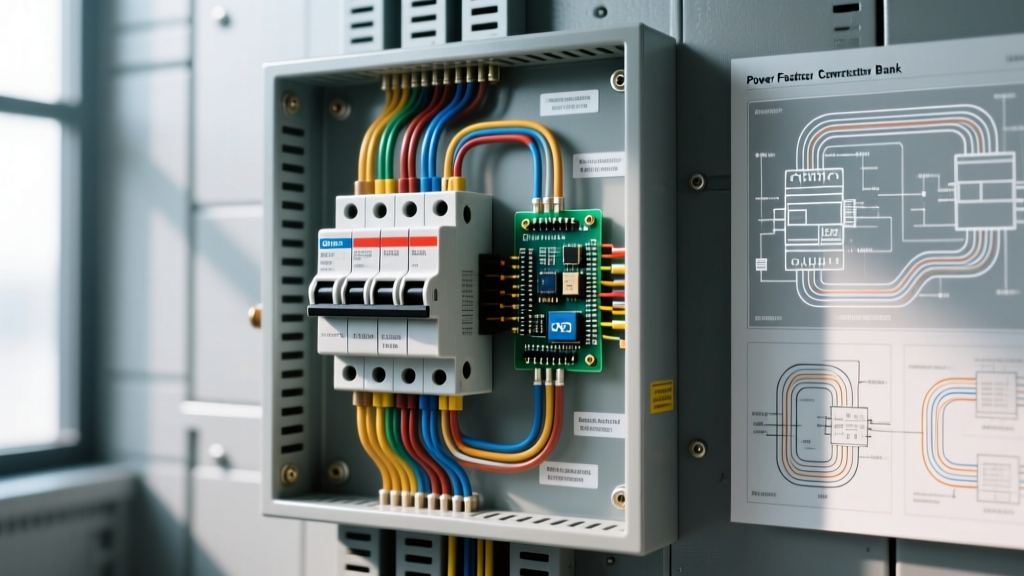
For a 15-amp circuit, NEC Article 240.4(D) strictly limits you to 14 AWG copper wire. Using 12 AWG is acceptable but physically harder to work with in standard device boxes. We recommend using Southwire 14/2 NM-B (commonly known as Romex) for the main runs. At the panel, install a Eaton BR115 15-Amp Single Pole Type BR breaker. Since this is a bedroom, the NEC requires Combination-Type AFCI protection. You will either use an Eaton BR115AF (AFCI breaker) or install a dual-function AFCI/GFCI receptacle at the first outlet in the circuit.
Step 2: Panel to First Device Routing
- Fish the Cable: Run the 14/2 NM-B from the main service panel to the first device box (usually the receptacle closest to the panel). Leave 8 inches of slack inside the box.
- Strip the Sheath: Use a Romex ripper to remove at least 3/4 inch of the outer jacket inside the box, ensuring no bare copper is exposed outside the clamp.
- Terminate at Panel: Connect the bare copper to the ground bar, the white neutral to the neutral bar, and the black hot to the AFCI breaker's pigtail/terminal.
Step 3: Daisy-Chaining Receptacles and Switches
The diagram will show a 'daisy chain' or parallel wiring configuration. Power flows from the panel to Receptacle A, then to Receptacle B, and finally to the switch and light fixture.
- At Receptacle A: Connect incoming black to the brass screw, incoming white to the silver screw, and bare copper to the green ground screw. Run a second 14/2 cable out to Receptacle B, connecting the new wires to the secondary set of terminal screws on the device (using Leviton T5320-W Tamper-Resistant receptacles).
- At the Switch Loop: When the diagram routes power to a ceiling light via a single-pole switch, use a 14/2 cable from the light box down to the switch box. Pro-Tip: Per NEC 2023/2026 updates, you must use the white wire as a hot supply to the switch. Mark it with black electrical tape at both ends, and connect it to the bottom brass screw on the switch (e.g., Lutron S-600-WH). The black wire returns the switched hot to the light fixture's black lead.
Expert Warning: Never use 'backstab' or push-in wire connections on the back of receptacles or switches. Under continuous 12A-14A loads, the internal spring contacts in backstabs degrade, causing high-resistance arcing. Always use the side terminal screws or screw-down back-wire clamps.
Real-World Edge Cases and Failure Modes
Even with a clear simple house electrical wiring diagram, field conditions introduce variables that can cause failures if ignored.
Shared Neutrals (Multi-Wire Branch Circuits)
If your diagram shows two hot wires (black and red) sharing a single white neutral, you are dealing with a Multi-Wire Branch Circuit (MWBC). You must use a 2-pole breaker or a handle tie (e.g., Eaton HT100) to ensure both ungrounded conductors disconnect simultaneously. Failing to do this violates NEC 210.4(B) and creates a lethal shock hazard for anyone servicing the neutral.
Box Fill Calculations
Overcrowding wires in a junction box causes heat buildup. According to NEC Article 314.16, a standard single-gang plastic box (approx. 18 cubic inches) can safely hold only four 14 AWG cables (assuming devices and clamps are factored into the fill calculation). If your diagram calls for four cables meeting at one switch, you must upgrade to a 22.5 cubic inch deep box.
Material Cost Breakdown (2026 Estimates)
Budgeting for a single 15-amp bedroom circuit requires accounting for current copper prices and smart-code compliant devices.
| Component | Specific Model / Type | Estimated Cost (USD) |
|---|---|---|
| Circuit Breaker (AFCI) | Eaton BR115AF 15A Single Pole | $48.00 - $55.00 |
| Wire (250 ft roll) | Southwire 14/2 NM-B Solid | $95.00 - $110.00 |
| Receptacles (Qty 5) | Leviton T5320-W 15A Tamper-Resistant | $15.00 ($3.00/ea) |
| Single Pole Switch | Lutron S-600-WH | $6.50 |
| Device Boxes (Qty 6) | Carlon B114B-UPC 1-Gang 14cu.in. | $5.40 ($0.90/ea) |
| Wire Nuts / Pigtails | Ideal Wire-Nut Assorted Kit | $12.00 |
| Total Estimated Material Cost | $181.90 - $203.90 | |
Frequently Asked Questions
Can I use 12 AWG wire on a 15-amp breaker?
Yes. NEC allows using a larger wire gauge than the minimum required. 12 AWG wire on a 15-amp breaker is perfectly safe and reduces voltage drop on runs exceeding 75 feet. However, 12 AWG is stiffer and harder to fold into standard single-gang boxes.
Why does my diagram show a white wire connected to a black wire?
This indicates a 'switch loop.' The white wire is being used to carry continuous hot power down to the switch, while the black wire carries the switched hot back up to the light. The NEC requires the white wire in this scenario to be permanently re-identified with black tape or marker to indicate it is a hot conductor.
Do I need a permit to follow this simple house electrical wiring diagram?
In almost all US jurisdictions, adding a new circuit or extending an existing one requires a municipal electrical permit and a subsequent inspection. The U.S. Consumer Product Safety Commission (CPSC) strongly advises against unpermitted DIY electrical work, as it can void home insurance policies in the event of an electrical fire.
Final Verification Before Energizing
Once all devices are terminated and the diagram is fully executed, do not immediately throw the breaker. Use a digital multimeter (such as the Fluke 117 True-RMS) set to continuity mode to test between the hot and neutral, and hot and ground at the panel. If the meter reads zero ohms or beeps, you have a dead short. Find and fix it before energizing. Only when the multimeter reads 'OL' (Open Loop) should you turn on the Eaton AFCI breaker and test the circuit.