
The Complete Hydronic Zoning Walkthrough
Upgrading a single-loop hydronic heating system into a multi-zone setup is one of the most effective ways to reduce energy waste and eliminate cold spots in residential and light-commercial buildings. According to the U.S. Department of Energy, properly implemented hydronic zoning can reduce heating energy consumption by up to 20% by preventing unoccupied rooms from receiving heated water. However, the electrical control side of this upgrade—specifically the wiring diagram for zone valves on boiler systems—is where most DIYers and junior technicians make critical errors.
This guide provides a comprehensive, step-by-step wiring walkthrough for integrating 24V AC zone valves with your boiler’s aquastat, circulator pump, and thermostats. We will focus on the industry-standard Honeywell V8043E and Taco 571-2 series valves, detailing exact terminal designations, transformer sizing, and edge-case troubleshooting.
⚠️ Critical Safety Warning
Boiler control panels contain 120V AC line voltage alongside 24V AC control circuits. Always shut off the dedicated 15A or 20A breaker supplying the boiler before opening the junction box. Use a non-contact voltage tester (NCVT) and a digital multimeter (DMM) to verify zero voltage on the main terminal blocks before proceeding.
Component Matrix: Zone Valve Power & VA Requirements
Before pulling a single wire, you must calculate your transformer load. A standard 40VA transformer will easily handle multiple Honeywell valves, but it will instantly burn out if overloaded with high-draw Taco valves. Always consult the Taco Comfort Solutions Literature Library or Honeywell spec sheets for exact inrush currents.
| Zone Valve Model | Actuator Type | Inrush Current (A) | Holding VA | End Switch Rating |
|---|---|---|---|---|
| Honeywell V8043E1012 | Heat Motor | 0.2A (4.8 VA) | 7.4 VA | 1.5A @ 120V (Tied to C) |
| Taco 571-2 | Thermal Wax | 0.8A (19.2 VA) | 12.0 VA | 1.5A @ 120V (Tied to C) |
| White-Rodgers 1361-102 | Heat Motor | 0.25A (6.0 VA) | 6.5 VA | Isolated SPST (Up to 120V) |
Pro Tip: If your system uses three Taco 571-2 valves, the combined inrush current when all thermostats call for heat simultaneously is 2.4A (57.6 VA). You must upgrade to a 75VA or 100VA 24V AC transformer (typically $35–$55 in 2026) to prevent voltage sag and transformer failure.
Pre-Wiring Preparation & Wire Selection
Adhering to NFPA 70 (National Electrical Code) Article 725 for Class 2 circuits is essential for low-voltage control wiring.
- 24V Control Circuits: Use 18 AWG solid copper thermostat wire (2-conductor for valve power, 3-conductor if running dedicated end-switch lines back to a centralized relay panel).
- 120V Line Circuits: Use 14 AWG stranded or solid THHN/THWN for circulator pump feeds and main transformer primaries.
- Tools Required: Wire strippers (18-10 AWG), DMM, 3/8' nut driver, and a label maker for circuit identification.
Step-by-Step Wiring Walkthrough: Honeywell V8043E
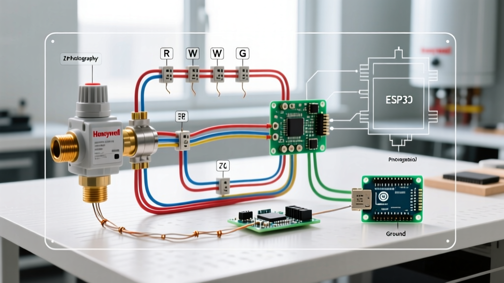
The Honeywell V8043E features three screw terminals: 1, 2, and 3. Terminal 2 is the common point shared by both the heat motor and the internal end switch. Understanding this shared common is the key to mastering the wiring diagram for zone valves on boiler systems.
Step 1: Powering the 24V Transformer
Mount your 40VA (or 75VA) 24V transformer inside the boiler junction box or a dedicated NEMA enclosure. Wire the 120V primary side to a switched hot line (often controlled by the boiler’s main service switch or an emergency shut-off).
- Transformer Primary (120V): Connect Black to Line (Hot), White to Neutral, and Green to Earth Ground.
- Transformer Secondary (24V): Designate one 24V terminal as R (Hot) and the other as C (Common). Mark the C terminal with blue electrical tape for visual consistency.
Step 2: Thermostat to Zone Valve Motor (Terminals 1 & 2)
Run 18/2 thermostat wire from the wall thermostat to the zone valve junction box.
- Connect the Rh/Rc (Power) terminal on the thermostat to the R (24V Hot) terminal on the transformer.
- Connect the W (Heat Call) terminal on the thermostat to Terminal 1 on the Honeywell V8043E.
- Connect Terminal 2 on the zone valve directly to the C (24V Common) terminal on the transformer.
Logic Check: When the thermostat calls for heat, it closes the internal relay, sending 24V AC from R, through the W wire, into Terminal 1, and returning via Terminal 2 to C. The heat motor energizes and slowly opens the brass valve body over 15 to 30 seconds.
Step 3: The End Switch & Boiler Activation (Terminals 2 & 3)
This is the most critical safety and operational step. The boiler must never fire and circulate water if the zone valve is closed, as this causes 'dead-heading' (pumping against a closed valve), which can overheat the pump and crack the boiler heat exchanger.
The internal end switch only closes after the valve is 100% open. Because Terminal 2 is tied to C, Terminal 3 acts as a switched Common.
- Run a wire from Terminal 3 on the zone valve to the T-T (Thermostat) terminal on the boiler’s aquastat or the TT input on your circulator relay (e.g., Taco SR504 or Honeywell R8845).
- Connect the other T-T terminal on the aquastat/relay back to the transformer's R (24V Hot) (or use a dedicated 24V R feed from the relay board).
Operational Sequence: Thermostat calls -> Valve Motor opens -> End switch closes (connecting Term 2 to Term 3) -> 24V circuit to the boiler aquastat is completed -> Boiler fires and circulator pump engages.
Integrating Smart Thermostats (2026 Standards)
Modern hydronic systems frequently utilize smart thermostats like the Ecobee SmartThermostat or Nest Learning Thermostat. These devices require a dedicated C-wire (Common) at the wall to power their Wi-Fi radios and backlit displays.
If your zone valve wiring only utilizes a 2-wire setup (R and W) to the wall, the smart thermostat will 'steal' power through the valve motor, causing the valve to chatter or fail to open fully. Solution: Always pull 18/3 or 18/5 thermostat wire to the wall. Connect the third wire to the transformer's C terminal at the zone valve junction box, and attach it to the C terminal on the smart thermostat baseplate. This provides a dedicated 24V return path, isolating the smart thermostat's power draw from the zone valve's heat motor circuit.
Real-World Troubleshooting & Edge Cases
1. Ghost Voltage and Valve Chatter
Field Insight: In large homes where 18 AWG thermostat wires are run parallel to 120V Romex for over 50 feet, electromagnetic induction can create 'ghost voltage' (typically 10V–15V AC) on the W wire. This phantom voltage can cause the zone valve heat motor to hum, overheat, and fail prematurely.
The Fix: Keep low-voltage wiring at least 2 inches away from line-voltage wiring. If ghost voltage persists, install a 100-ohm, 2-watt bleeder resistor across Terminals 1 and 2 at the zone valve to dissipate the induced current.
2. The 'Fast-Cycle' Boiler Short-Cycling
If your boiler fires, runs for 45 seconds, and shuts off while the zone valve is still opening, your aquastat's high-limit switch is tripping. This happens when the boiler fires before the zone valve has fully opened, or if the system lacks a primary-secondary piping loop (hydraulic separation). Ensure your wiring diagram strictly routes the end switch (Terminal 3) before the boiler's TT terminals, never in parallel with a manual override switch that could bypass the end-switch safety delay.
3. Multi-Zone Transformer Burnout
If a 40VA transformer is hot to the touch and emits a faint burning ozone smell, you have exceeded its VA rating. As noted in our component matrix, mixing Honeywell and Taco valves on the same secondary loop without calculating the combined inrush VA is a leading cause of mid-winter system failures. Always upgrade to a 75VA transformer (e.g., Honeywell AT72D1683) when wiring more than three standard motorized valves, or use isolated Taco IFS series valves with internal relays to offload the transformer.
Final Verification Checklist
Before restoring 120V power to the boiler, perform a continuity check with your DMM:
- Verify 0 ohms (continuity) between the boiler chassis and the earth ground wire.
- Verify infinite resistance (OL) between the 24V R and C terminals to ensure no dead shorts exist in the wall thermostat wiring.
- Manually push the manual opener lever on the zone valve. Use the DMM to verify continuity between Terminals 2 and 3. Release the lever; the circuit should open immediately.
By strictly following this wiring diagram for zone valves on boiler systems, you ensure a safe, efficient, and code-compliant hydronic heating setup that will reliably serve the building for decades.