
The Hidden Dangers of Non-Compliant 24V Marine Wiring
Electrical fires remain one of the leading causes of marine vessel losses. When upgrading to high-thrust 24V trolling motors like the Minn Kota Terrova 80 or the Lowrance Ghost, many DIY boaters rely on generic automotive wiring practices. This is a critical mistake. Marine environments introduce saltwater corrosion, constant vibration, and high humidity, all of which rapidly degrade standard copper and inadequate overcurrent protection.
As of 2026, the shift toward high-output Lithium Iron Phosphate (LiFePO4) marine batteries has changed the electrical landscape. LiFePO4 batteries can deliver massive inrush currents that will instantly weld undersized contacts or melt automotive-grade fuses. To ensure safety and pass marine insurance surveys, your wiring diagram for 24V trolling motor installations must strictly adhere to the American Boat and Yacht Council (ABYC) E-11 standards. This guide provides an expert-level, code-compliant schematic breakdown, component selection matrix, and installation protocol.
The ABYC-Compliant Wiring Diagram for 24V Trolling Motor
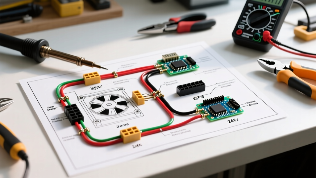
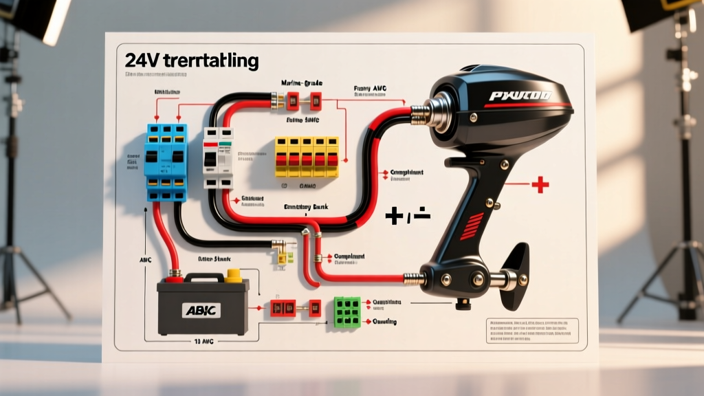
Because visual schematics can be misinterpreted, below is the exact node-by-node textual wiring diagram for a 24V system utilizing two 12V batteries in series, compliant with ABYC E-11 AC & DC Electrical Systems guidelines.
Node 1: The 24V Battery Bank (Series Configuration)12V Battery A (Negative) -> Connects to 12V Battery B (Positive) via 4 AWG series link.
Node 2: Positive Power Run & Overcurrent Protection
12V Battery B (Positive) -> 4 AWG Marine Wire -> 60A Thermal Circuit Breaker (Mounted within 7 inches of the positive terminal).
Breaker Output -> 6 AWG (or 4 AWG) Tinned Marine Wire -> Runs to Bow Receptacle (Positive Pin).
Node 3: Negative Power Run & Shunt
12V Battery A (Negative) -> 4 AWG Marine Wire -> 500A/50mV Battery Monitor Shunt.
Shunt Output -> 6 AWG (or 4 AWG) Tinned Marine Wire -> Runs to Bow Receptacle (Negative Pin).
Node 4: The Bow Connection
Receptacle Positive Pin -> Heavy Duty Plug -> Trolling Motor Positive Lead.
Receptacle Negative Pin -> Heavy Duty Plug -> Trolling Motor Negative Lead.
Expert Note on Jumper Cables: The series link connecting Battery A and Battery B must be of the same wire gauge (or thicker) than the main supply cables. Using a thin, off-the-shelf automotive jumper cable for the series link is a severe bottleneck that will cause localized heating and voltage drop under heavy trolling motor loads.
Component Selection: Meeting the 2026 Marine Standard
Sourcing the correct components is where most DIY installations fail ABYC compliance. Below is a comparison matrix contrasting big-box store shortcuts with professional marine-grade requirements.
| Component | Non-Compliant (Automotive/Big Box) | ABYC Compliant (Marine Grade) | Estimated 2026 Cost |
|---|---|---|---|
| Wire Type | CCA (Copper Clad Aluminum), untinned | Ancor Marine Grade Tinned Copper (Type 3 stranding) | $2.20 - $3.50 / ft |
| Terminals | Standard vinyl insulated crimps | Dual-wall adhesive heat shrink (e.g., 3M MDT) | $1.50 - $2.00 / ea |
| Overcurrent | Automotive ANL fuse or glass tube | Blue Sea 285-Series Thermal Breaker (60A) | $45.00 - $55.00 |
| Receptacle | Standard 3-prong twist lock | Marinco 201CRS 24V/36V 50A Locking Receptacle | $85.00 - $110.00 |
Wire Gauge Sizing and Voltage Drop Mathematics
The ABYC mandates a maximum 3% voltage drop for critical navigation and maneuverability electronics. While a trolling motor is technically categorized under the 10% 'non-critical' threshold by older standards, modern brushless motors (like the Lowrance Ghost) rely on precise voltage regulation for their internal sonar and GPS anchoring features. A voltage drop exceeding 3% will trigger low-voltage cut-offs and degrade motor torque.
Calculating Your Specific Run
Use the following formula to determine your exact wire gauge requirement:
Voltage Drop (VD) = Current (I) × Wire Resistance (R) × Total Length (L)
- Current (I): An 80 lb thrust 24V motor draws roughly 40A at maximum speed. (Check your specific motor's max amp draw; the Minn Kota Terrova 80 draws 56A max).
- Total Length (L): Measure the positive run from the battery to the motor, AND the negative return run. If the battery is in the stern and the motor is in the bow of a 20-foot bass boat, your total circuit length is roughly 45 feet.
- Wire Resistance (R): 6 AWG tinned copper has a resistance of roughly 0.0004 ohms per foot. 4 AWG is 0.00025 ohms per foot.
Scenario Calculation (6 AWG, 56A draw, 45ft total length):
VD = 56 × 0.0004 × 45 = 1.008 Volts.
Percentage Drop = (1.008 / 24) × 100 = 4.2%.
Verdict: 6 AWG fails the 3% optimal threshold for a 56A draw over 45 feet. You must upgrade to 4 AWG Ancor Marine Wire to drop the voltage loss below 3%, ensuring your LiFePO4 BMS does not prematurely trip during a heavy wind-fighting maneuver.
Overcurrent Protection and Lithium Inrush Currents
According to Blue Sea Systems Circuit Protection guidelines, overcurrent devices must be rated for the continuous load plus a safety margin, while also handling inrush currents. When you engage a modern 24V trolling motor, the capacitors in the motor's ESC (Electronic Speed Controller) draw a massive instantaneous spike of current.
If you use a standard fast-blow fuse, this inrush spike will blow the fuse every time you tap the pedal. You must use a Thermal Magnetic Circuit Breaker or a Slow-Blow Class T Fuse. The Blue Sea Systems 7182 (60A) Thermal Breaker is specifically designed with a time-delay curve that ignores the millisecond inrush spike of trolling motors but will instantly trip if a dead short occurs in the bow wiring.
Step-by-Step Installation & Crimping Protocol
Proper termination is just as critical as wire sizing. ABYC standards explicitly prohibit the use of solder-only connections in marine environments due to solder's brittleness under vibration. You must use mechanical crimps.
- Strip the Wire: Use a precision wire stripper to remove exactly 5/8' of insulation from the 4 AWG Ancor wire. Do not nick the copper strands; nicked strands create localized hot spots.
- Insert the Terminal: Slide the 4 AWG adhesive-lined heat shrink ring terminal onto the wire. Ensure all strands are twisted tightly and fully inserted into the copper barrel.
- Ratchet Crimp: Use a calibrated ratcheting crimper (such as the Knoweasy Heavy Duty or Knipex crimping tool) set to the 4 AWG die. The ratchet must complete the full cycle to ensure the exact compression ratio required for a gas-tight seal.
- Heat Shrink: Apply heat evenly using a heat gun (not a lighter) at roughly 250°F until the adhesive sealant purges slightly from the edges. This creates a waterproof, salt-spray-proof barrier.
- Torque Specifications: When attaching the ring terminals to the battery studs and breaker lugs, use a torque wrench set to 48 in-lbs (for standard 1/4' or 5/16' marine studs). Under-torquing causes arcing; over-torquing strips the soft copper studs.
Troubleshooting Common 24V Failure Modes
Even with a perfect wiring diagram for 24V trolling motor setup, environmental factors can cause issues. Here is how to diagnose the most common 2026 marine electrical faults:
- Motor Cuts Out Under Heavy Load: Usually caused by a tripping BMS on LiFePO4 batteries. Check if your breaker is sized correctly, and ensure your battery's continuous discharge rating (CDR) exceeds the motor's max draw by at least 20%.
- Corrosion at the Bow Receptacle: If you used non-marine dielectric grease, it may have washed away. Clean the Marinco receptacle pins with an electrical contact cleaner and apply a heavy coat of marine-grade anhydrous calcium sulfonate grease (e.g., Lucas Oil Marine Grease).
- Intermittent Power Loss: Inspect the series link between the two 12V batteries. Vibration often loosens the nut on the interconnecting stud. Re-torque to 48 in-lbs and apply a corrosion inhibitor spray.
By adhering strictly to these ABYC guidelines, utilizing marine-grade tinned copper, and calculating your specific voltage drop, you ensure your 24V trolling motor operates safely, efficiently, and reliably for years to come. For further reading on federal safety requirements, consult the USCG Boating Safety portal regarding electrical system inspections.