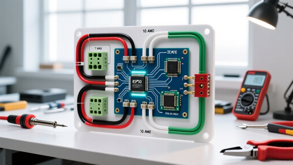

Panel & Breaker Integration: The Foundation of Trailer Braking
When towing a 5,000 lb to 15,000 lb trailer, the electric trailer brake controller is the brain of your stopping power, but the wiring and circuit protection act as the central nervous system. A flawed electric trailer brake controller wiring diagram implementation doesn't just result in a blown fuse; it can lead to catastrophic brake failure on a downhill grade. While most DIY guides focus solely on splicing wires under the dash, true electrical safety begins at the power source: the 12V DC distribution panel and the primary circuit breaker.
In this comprehensive guide, we approach the brake controller installation from a Panel & Breaker Guide perspective. We will cover exact auto-reset breaker sizing, SAE-compliant wire gauge selection, voltage drop mitigation, and the precise routing required for top-tier 2026 units like the Tekonsha Prodigy P3 (Part #90195) and the Redarc Tow-Pro Elite V3 (Part #EBRH-ACCV3).
DC Circuit Protection: Sizing the Auto-Reset Breaker
A common and dangerous mistake is treating a 12V DC automotive electrical system like a 120V AC residential panel. Standard AC thermal-magnetic breakers are not rated for DC arc suppression. For a trailer brake controller, you must use a DC-rated auto-reset thermal circuit breaker, typically mounted within 18 inches of the vehicle's battery positive terminal or integrated into a dedicated high-amperage DC fuse block.
Why 30A vs. 40A?
A standard dual-axle trailer features four electric brakes. Each brake magnet draws approximately 3.5 to 4.0 amps at 12V DC under full load. Four magnets equal roughly 16 amps of continuous draw. However, the initial inrush current (surge) when the controller pulses the brakes can spike to 25+ amps.
- 30-Amp Breaker (e.g., Bussmann CB181-30): The industry standard for single and dual-axle trailers (up to 4 brakes). It handles the inrush spike without nuisance tripping while protecting 10 AWG wire from melting during a dead short.
- 40-Amp Breaker (e.g., Bussmann CB181-40): Required for heavy-duty tri-axle trailers (6 brakes) or when running a dedicated 12V auxiliary charge line parallel to the brake circuit. Requires an upgrade to 8 AWG wire.
CRITICAL SAFETY WARNING: Never use a standard glass AGC/MDL fuse or an AC residential breaker for the primary brake controller power feed. Glass fuses cannot handle the thermal cycling of brake surges and will fatigue, while AC breakers will sustain a DC electrical arc, potentially causing an under-hood fire. Always use a DC-rated, surface-mount auto-reset breaker.
Wire Gauge Selection & Voltage Drop Matrix
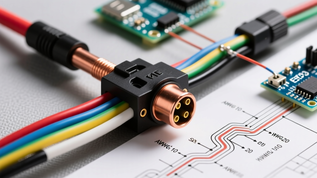
Electric brake magnets are highly sensitive to voltage drop. If your controller outputs 12V, but the wiring resistance drops the voltage to 9V at the trailer axle, your braking force is reduced by over 30%. According to SAE J1128 standards for automotive primary wire, you must size your wire based on the total run length (battery to controller, plus controller to the 7-way rear bumper plug).
| Total Wire Run Length | Recommended Wire Gauge | Max Continuous Amperage | Expected Voltage Drop (at 15A) | Trailer Application |
|---|---|---|---|---|
| Under 15 Feet | 12 AWG Stranded | 20A | < 2.0% | Single Axle (2 Brakes) |
| 15 to 25 Feet | 10 AWG Stranded | 30A | < 2.5% | Dual Axle (4 Brakes) - Standard |
| 25 to 40 Feet | 8 AWG Stranded | 40A | < 2.8% | Tri-Axle (6 Brakes) / Long Bed |
Note: Always use pure copper, multi-strand SAE J1128 wire. Avoid Copper-Clad Aluminum (CCA) wire sold in budget auto parts kits, as it has 40% higher resistance and is prone to snapping under chassis vibration.
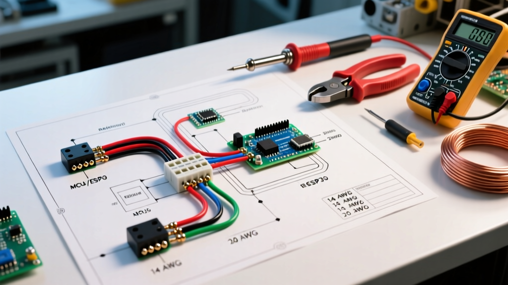
The Universal Electric Trailer Brake Controller Wiring Diagram
Whether you are installing an aftermarket proportional controller or repairing the umbilical wiring for an OEM Integrated Trailer Brake Module (ITBM) found in 2026 Ford F-150s and Ram 2500s, the core routing topology remains identical. Below is the step-by-step physical routing sequence.
- Battery to Breaker (Black Wire, 10 AWG): Run a 10 AWG black wire from the positive battery terminal to the 'BAT' stud on the 30A auto-reset breaker. Keep this run under 18 inches.
- Breaker to Controller (Black Wire, 10 AWG): Route a second 10 AWG black wire from the 'AUX' stud on the breaker through the firewall (using a rubber grommet) directly to the brake controller's power input pigtail.
- Controller Ground (White Wire, 10 AWG): The ground wire must be routed directly to the vehicle's negative battery terminal or a verified, bare-metal chassis ground tied directly to the engine block. Do not ground to a painted dash bracket.
- Stoplight Switch (Red Wire, 18 AWG): Splice the red wire into the 'cold' side of the brake pedal switch. This wire only carries a low-amperage signal (under 1A) to tell the controller you are pressing the brake pedal.
- Brake Output to 7-Way (Blue Wire, 10 AWG): Route the blue output wire from the controller to the rear of the vehicle, terminating at Pin 4 of the 7-way RV blade connector.
7-Way RV Blade Pinout (SAE J286 Standard)
Understanding the 7-way connector is vital for panel-to-trailer troubleshooting. When looking at the vehicle-side receptacle with the hinged door at the top, the pinout is as follows:
- Pin 1 (Left Center): Tail/Running Lights (Brown)
- Pin 2 (Top Right): 12V Auxiliary Power (Black) - Often wired to a separate 40A breaker for trailer battery charging.
- Pin 3 (Bottom Center): Ground (White) - Must be 10 AWG or 8 AWG to handle the return current of all trailer circuits.
- Pin 4 (Top Left): Electric Brakes (Blue) - Direct feed from the brake controller.
- Pin 5 (Right Center): Right Turn/Stop (Green)
- Pin 6 (Bottom Left): Left Turn/Stop (Yellow)
- Pin 7 (Bottom Right): Reverse Lights (Purple)
2026 Context: OEM ITBM vs. Aftermarket Integration
As of 2026, over 75% of heavy-duty trucks come equipped with factory Integrated Trailer Brake Modules (ITBM). The wiring diagram for an ITBM differs slightly: the controller is housed in the dash, but the power feed and output wiring still rely on the under-hood DC distribution panel. If an OEM ITBM fails or throws a 'Trailer Wiring Fault' code due to a burnt internal relay, many fleet managers and DIYers bypass the ITBM by installing a Redarc Tow-Pro Elite V3. When doing this, you must tap into the factory blue brake output wire located under the driver's kick panel, but you must still verify the under-hood 30A breaker is intact and feeding the 7-way plug.
Advanced Troubleshooting: Panel & Breaker Failure Modes
When your brake controller displays an error code, the issue is rarely the digital unit itself. Use this diagnostic matrix to trace the fault back to the panel and wiring:
1. Controller Reads 'SH' (Short Circuit)
The Cause: The blue output wire is touching the chassis ground, or the 7-way plug has internal corrosion bridging Pin 4 (Brakes) and Pin 3 (Ground).
The Fix: Inspect the 7-way receptacle. If the breaker is tripping instantly, use a multimeter to check continuity between the blue wire and the chassis. Check the rear wiring harness for pinch points near the bumper.
2. Controller Reads 'OL' (Overload) or Breaker Trips Continuously
The Cause: You are pulling a tri-axle trailer (6 brakes) on a 30A breaker, or one of the trailer's brake magnets has failed internally and is drawing excessive amperage.
The Fix: Measure the amperage at the 7-way Pin 4 using a DC clamp meter while a helper applies the manual override slider. If draw exceeds 28A, upgrade to a 40A breaker and 8 AWG wire, or inspect the trailer magnets for melted casings.
3. Weak Braking / Controller Maxed Out but Trailer Won't Stop
The Cause: Severe voltage drop. The controller is outputting 12V, but undersized 12 AWG wire or a corroded ground at Pin 3 is dropping the voltage to 8V at the trailer axles.
The Fix: Perform a loaded voltage drop test. Place your multimeter probes directly on the trailer's brake magnet wires while the brakes are engaged. If you read less than 11.5V, clean the 7-way pins with dielectric grease and upgrade the vehicle-side ground wire to 8 AWG.
Authoritative References & Standards
For further reading on automotive DC electrical standards and towing safety, consult the following industry resources:
- For comprehensive 7-way pinout diagrams and vehicle-specific wiring adapters, refer to etrailer's comprehensive trailer wiring guide.
- For official installation schematics and error-code diagnostics for proportional controllers, visit the Tekonsha official support and wiring manuals portal.
- For manufacturing and safety compliance standards regarding RV and trailer electrical systems, review the RV Industry Association (RVIA) standards documentation.
By treating your brake controller installation as a critical DC panel integration rather than a simple accessory splice, you ensure maximum stopping power, eliminate nuisance breaker trips, and guarantee safety on the steepest mountain passes.