
Adapting Residential Comfort for the Road: The RV Dual-Switch Challenge
Upgrading the interior of an RV, Sprinter van, or Skoolie often involves bringing residential comforts to a mobile environment. One of the most popular upgrades is installing a low-profile 120V AC ceiling fan with an integrated LED light kit. However, finding a standard wiring diagram for ceiling fan with two switches online usually assumes a static, residential build. When you are wiring a vehicle, the rules of physics—specifically vibration, thermal expansion, and inverter power quality—change the game entirely.
In this vehicle-specific guide, we will walk through the exact wiring diagram for a dual-switch ceiling fan setup (one switch for the fan motor, one for the light kit) on an RV's 120V AC branch circuit. We will also cover the critical hardware substitutions required to ensure your connections do not arc, melt, or fail while driving down the highway.
Why Vehicle Environments Change the Wiring Rules
Before pulling any wire, you must understand why standard residential practices fail in mobile applications. An RV's 120V AC system is powered either by shore power or an onboard inverter/charger (like a Victron MultiPlus). The electrical topology is the same as a house, but the physical environment is hostile.
The Danger of Solid Core Wire
Residential wiring typically uses solid copper Romex (NM-B). In a vehicle, the chassis flexes, vibrates, and experiences extreme temperature swings. Solid core wire will suffer from metal fatigue and eventually snap inside the insulation, creating a hidden fire hazard. Rule #1 of vehicle wiring: Always use stranded wire for 120V AC branch circuits. We recommend 14 AWG Stranded THHN/THWN-2 wire, which is rated for 15A circuits and highly resistant to vibration fatigue.
Wire Nuts vs. Lever Connectors
Standard twist-on wire nuts rely on friction and the twisting of solid copper wires to maintain contact. In a high-vibration environment, wire nuts will back off over time. According to industry testing on mobile electrical systems, push-in lever connectors are the only reliable choice for junction boxes in vehicles. The WAGO 221 Series Lever-Nuts use a spring-pressure mechanism that maintains constant contact force on stranded wire, regardless of vibration or thermal cycling.
Materials & Component List (2026 Pricing)
- Ceiling Fan: Hunter Sea Wind 48-inch or Minka-Aire Concept II (Low-profile, 120V AC, ~$150-$250). Ensure it has separate blue (light) and black (motor) hot wires.
- Wall Switch: Leviton 5241 Dual Single-Pole Toggle Switch (~$12). This fits in a standard single-gang box but houses two independent switches.
- Wire: 14 AWG Stranded THHN (Black, Red, White, Green/Bare). (~$0.75/ft).
- Connectors: WAGO 221 Series (3-conductor and 5-conductor lever nuts). (~$0.60 each).
- Mounting Hardware: Toggle bolts or rivet nuts (Rivnuts) for securing the fan bracket to the RV's thin ceiling substrate or aluminum extrusions.
Wiring Diagram: 120V AC Dual Switch Setup
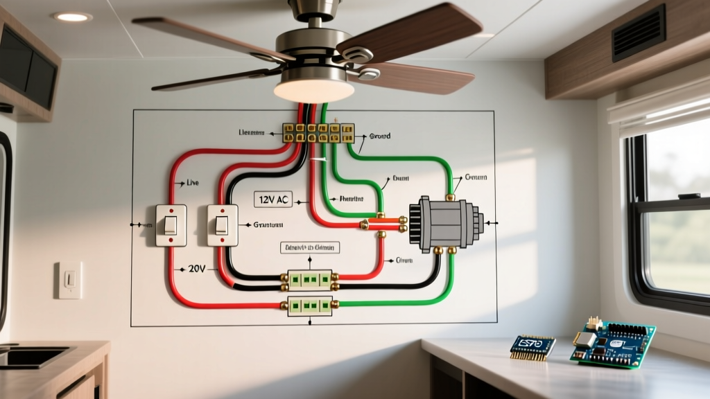
The electrical logic for this setup requires running a 3-wire cable (plus ground) from the switch box to the ceiling canopy. This provides a constant neutral, a constant ground, and two separate 'switched hot' legs.
Step 1: The Switch Box (Wall Location)
Power enters the wall switch box from your RV's 120V AC breaker panel. You will need a 15A breaker dedicated to this circuit.
- Line In (Power Source): Connect the incoming Black (Hot) wire to the common 'Line' terminal (usually the brass screw) on the bottom of the Leviton 5241 dual switch.
- Load 1 (Fan Motor): Connect a Black stranded wire to the top terminal of Switch 1. This will run up to the ceiling and connect to the fan's Black wire.
- Load 2 (Light Kit): Connect a Red stranded wire to the top terminal of Switch 2. This will run up to the ceiling and connect to the fan's Blue wire.
- Neutral Bypass: The incoming White (Neutral) wire does not connect to the switch. Use a WAGO 3-conductor lever nut to splice the incoming White wire directly to the White wire running up to the ceiling.
- Ground: Splice all bare/green ground wires together with a WAGO connector and pigtail to the metal switch box and the switch's green ground screw.
Step 2: The Ceiling Canopy (Fan Location)
At the ceiling, you will have three wires coming from the wall (Black, Red, White) plus the ground, and four wires coming from the fan (Black, Blue, White, Green).
- Fan Motor: Connect the Black wire from the wall (Switch 1) to the Black wire from the fan motor using a WAGO connector.
- Light Kit: Connect the Red wire from the wall (Switch 2) to the Blue wire from the fan light kit.
- Neutral: Connect the White wire from the wall to the White wire from the fan.
- Ground: Connect the bare ground from the wall to the Green ground from the fan, and bond it to the metal ceiling mounting bracket.
Pro-Tip for RV Ceilings: RV ceilings are often made of thin luan plywood or PVC panels. Never rely solely on wood screws to hold a 25 lb ceiling fan. Use a backing plate of 3/4-inch plywood secured to the roof trusses, or use steel Rivnuts bolted directly into the aluminum chassis framing to support the fan's dynamic weight and torque.
Comparison: Vibration-Proof Connectors
Choosing the right connector is the difference between a safe rig and an electrical fire. Here is how standard residential connectors hold up in mobile applications.
| Connector Type | Vibration Resistance | Stranded Wire Compatibility | Verdict for RV Use |
|---|---|---|---|
| Standard Twist-On Wire Nuts | Poor | Moderate (Requires pre-twisting) | Avoid. High failure rate in mobile environments. |
| Crimp Sleeves | Excellent | Excellent | Good, but requires specialized crimping tool and heat shrink. |
| WAGO 221 Lever-Nuts | Excellent | Excellent | Best Choice. Tool-free, inspectable, and immune to vibration loosening. |
Inverter Compatibility & Failure Modes
When boondocking, your ceiling fan will be powered by your RV's inverter. This introduces a critical variable: Waveform Quality.
The Modified Sine Wave Trap
Ceiling fan motors rely on a start capacitor and run capacitor to manage the phase shift of the AC current. If you run a ceiling fan on a cheaper Modified Sine Wave (MSW) inverter, the choppy, square-wave approximation of AC power will cause the motor to hum violently, overheat, and eventually destroy the capacitors within a few months. Furthermore, the integrated LED light driver may flicker or fail.
The Solution: You must use a Pure Sine Wave (PSW) inverter (such as the Victron Phoenix or MultiPlus series) to power inductive loads like fan motors. PSW inverters output a smooth waveform identical to the utility grid, ensuring the fan runs silently and efficiently. According to the National Electrical Code (NFPA 70) guidelines on power quality and mobile installations, ensuring compatible waveforms for inductive loads is essential for preventing thermal runaway in motor windings.
Voltage Drop Over Long Wire Runs
RVs can be 30 to 45 feet long. If your breaker panel is in the rear garage and your fan is in the front bedroom, a 14 AWG wire might experience noticeable voltage drop, causing the fan to run slower on high speed. If the one-way wire run exceeds 40 feet, upgrade to 12 AWG stranded wire to maintain a voltage drop of less than 3%.
Frequently Asked Questions
Can I use a 12V DC marine fan instead of a 120V AC residential fan?
Yes, 12V DC fans (like those from Caframo or Fantasea) are highly efficient and don't require an inverter. However, they do not use standard 'two switch' wall setups. They typically use a single integrated wall dial that controls both speed and dimming via PWM (Pulse Width Modulation). If you specifically want the classic dual-toggle wall switch setup, a 120V AC residential fan is the correct path.
Do I need to ground the fan to the RV chassis?
No. The 120V AC system in an RV is a floating, isolated system when running on an inverter, and it bonds to the shore-power ground when plugged in. You should bond the fan's ground wire to the AC grounding bus bar in your main breaker panel, not directly to the vehicle's steel chassis (which is reserved for 12V DC negative returns and chassis bonding).
Where can I find the manufacturer's specific wiring schematic?
While the logic above applies universally to dual-switch setups, always verify the color codes on your specific unit. You can download model-specific PDFs directly from the Hunter Fan Installation Guides archive or the respective manufacturer's support page before making your final connections.
Final Safety Checklist Before Energizing
- Verify the 15A AC breaker is in the OFF position.
- Ensure all WAGO lever connectors are fully closed and no bare copper is exposed outside the connector housing.
- Tug-test every stranded wire to ensure it is locked into the lever nut.
- Confirm the fan mounting bracket is secured to structural framing, not just the ceiling panel.
- Use a multimeter to verify 120V AC at the line-in before connecting the switch.
By respecting the unique physical demands of a vehicle environment and strictly following this wiring diagram for a ceiling fan with two switches, you will achieve a reliable, quiet, and safe climate control upgrade for your rig.