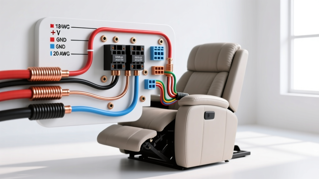

System Architecture: AC to DC Conversion in Lift Chairs
Repairing or building a custom mobility chair requires a precise understanding of the underlying electrical architecture. Unlike standard household AC appliances, the lift wiring diagram for electric recliner systems relies on a low-voltage DC ecosystem. Major manufacturers like Pride Mobility, Golden Technologies, and Lane utilize linear actuator motors (commonly branded by Okin, Limoss, or Kaidi) that operate on 24V DC or 29V DC.
The power delivery chain begins at a 120V AC wall outlet, feeding into a Class 2 switching power supply (transformer). This transformer steps the voltage down and rectifies it to DC, which then routes through a multi-channel control box before reaching the individual lift and recline actuators. Because these motors draw significant current under load—especially when elevating a user from a seated to a standing position—selecting the correct wire gauge and adhering to standardized color codes is critical to prevent voltage drop, thermal runaway, and control board resets.
Safety Notice: While the DC side of the circuit is considered low-voltage (Class 2 under NFPA 70 National Electrical Code Article 725), the AC primary side of the transformer carries lethal mains voltage. Always disconnect the AC power and verify zero voltage at the transformer output before probing the DC control box.
Wire Gauge Selection (AWG) for Linear Actuators
The most common point of failure in DIY recliner wiring and aftermarket lift kit installations is improper wire gauge selection. Linear actuators in lift chairs typically draw between 1.5A and 3.5A under peak mechanical load. While 18 AWG wire is standard for the short, pre-manufactured pigtails attached directly to the motor housing, extending these runs requires careful calculation to avoid voltage drop.
If the voltage at the motor terminals drops below 22V (on a 24V system) or 26V (on a 29V system) during operation, the internal Hall-effect sensors will fail to register rotor position, causing the control box to trigger a fault protection reset. According to resistance metrics outlined by the Engineering Toolbox AWG standards, copper wire resistance increases proportionally with length, directly impacting voltage delivery.
Wire Gauge vs. Amperage Matrix for 29V DC Lift Systems
| Wire Gauge (AWG) | Max Continuous Current | Max Run Length (One Way) | Application in Lift Recliner |
|---|---|---|---|
| 22 AWG | 0.92 A | 3 ft | Hall-effect sensor feedback lines only |
| 18 AWG | 2.3 A | 6 ft | Factory motor pigtails, short jumper cables |
| 16 AWG | 3.7 A | 12 ft | Extended runs from control box to footrest actuator |
| 14 AWG | 5.9 A | 20 ft | Heavy-duty lift columns, dual-motor parallel wiring |
Pro-Tip for Custom Builds: If you are routing wires through the floor to a remote battery backup or a centralized 29V power supply, always use 14 AWG stranded copper with a high-strand silicone jacket. Stranded wire is mandatory; solid core wire will fatigue and snap due to the constant vibration and articulation of the scissor-lift mechanism.
Industry Color Codes & Connector Pinouts
Electric recliners do not universally adhere to a single global color code, but the North American mobility market (dominated by Okin and Limoss components) has standardized around specific DIN and flat-blade connector configurations. Understanding these pinouts is essential when interpreting a lift wiring diagram for electric recliner troubleshooting.
The 2-Pin Power Connector (Standard Actuator)
Basic lift and recline motors without position feedback use a simple 2-pin setup. These are often housed in a proprietary quick-disconnect block (like the Okin OI-series or Kaidi KD-series).
- Red Wire: +29V DC (Positive)
- Black Wire: GND (Negative / Ground)
Note: Reversing the polarity on a standard 2-pin DC motor will simply reverse the direction of the actuator (e.g., extending instead of retracting). It will not damage the motor, but it will confuse the control box logic if not corrected.
The 5-Pin Connector (Smart Actuators with Encoders)
High-end lift chairs featuring memory positions (e.g., 'Zero Gravity' or 'Favorite Chair' presets) utilize actuators with built-in Hall-effect encoders. These require a 5-pin DIN or 5-pin flat connector to relay rotor position back to the microcontroller.
| Pin Number | Wire Color | Function | Voltage / Signal Type |
|---|---|---|---|
| Pin 1 | Red | Motor Power (+) | +29V DC |
| Pin 2 | Black | Motor Power (-) | GND |
| Pin 3 | White | Hall Sensor VCC | +5V DC (Logic Level) |
| Pin 4 | Blue / Green | Encoder Signal A | 0-5V Pulse (PWM) |
| Pin 5 | Yellow / Brown | Encoder Signal B | 0-5V Pulse (PWM) |
Critical Warning: Never apply 29V DC to Pins 3, 4, or 5. Doing so will instantly destroy the 5V logic board inside the actuator housing, rendering the $150+ motor useless. Always verify pinouts with a multimeter before applying power to an unmarked 5-pin harness.
Common Failure Modes in Lift Chair Wiring
When diagnosing a malfunctioning lift chair, the issue is rarely a burnt-out motor. Based on field repair data and FDA mobility device safety reports, the vast majority of electrical failures stem from wiring degradation and mechanical stress.
- Scissor-Mechanism Pinch Points: The most frequent cause of sudden failure is the 18 AWG motor wire getting caught in the steel scissor-lift arms. Over months of articulation, the insulation wears away, causing a dead short between the +29V and GND lines. This trips the internal thermal fuse inside the transformer.
- Control Box Relay Welding: If a user frequently actuates the chair while the transformer is undersized (e.g., using a 1.5A transformer on a dual-motor 3A system), the high inrush current can weld the contacts of the internal PCB relays shut. The chair will move in one direction but fail to reverse.
- Connector Oxidation: The 5-pin DIN connectors are highly susceptible to humidity and oxidation. A micro-layer of corrosion on the 5V logic pins (Pins 3-5) will cause the control box to lose encoder tracking, resulting in the chair 'stuttering' or stopping mid-lift.
Step-by-Step Multimeter Troubleshooting Protocol
Before replacing expensive components, follow this diagnostic sequence using a digital multimeter (DMM) to isolate the fault.
Step 1: Verify Transformer Open-Circuit Voltage
Disconnect the transformer from the control box. Set your DMM to DC Voltage. Probe the output barrel jack or proprietary DC plug. A healthy 29V transformer should read between 29.2V and 30.5V DC under no load. If it reads 0V or fluctuates wildly, the switching power supply has failed and must be replaced (Typical replacement cost: $35 - $55 for a Kaidi or Okin branded 29V 2A unit).
Step 2: Test Voltage Drop Under Load
Reconnect the system. Back-probe the DC input terminals on the control box while an assistant actuates the lift motor. If the voltage drops below 24V DC while the motor is running, you have excessive resistance in the line. Check for undersized extension wires or corroded inline barrel connectors.
Step 3: Isolate the Hall-Effect Sensor (5-Pin Motors)
If the motor runs but the chair stops randomly or fails to reach memory presets, the encoder is failing. Disconnect the 5-pin plug. Set the DMM to Continuity/Ohms. Measure between Pin 3 (White) and Pin 2 (Black/GND). You should read a high impedance (open circuit). If it reads near 0 ohms, the internal 5V voltage regulator inside the motor has shorted, requiring a full actuator replacement.
Final Considerations for 2026 Installations
As smart-home integration becomes standard in 2026 mobility furniture, newer control boxes feature Bluetooth and Wi-Fi modules that draw a continuous 0.5A standby current. When calculating wire gauge for the main DC trunk line from the transformer to the control box, you must now add this standby draw to the peak motor load. Always upsize your main DC trunk wire to 14 AWG to accommodate modern smart-recliner telemetry and ensure long-term thermal stability.