
Mastering the Toyota Electrical Wiring Diagram (EWD)
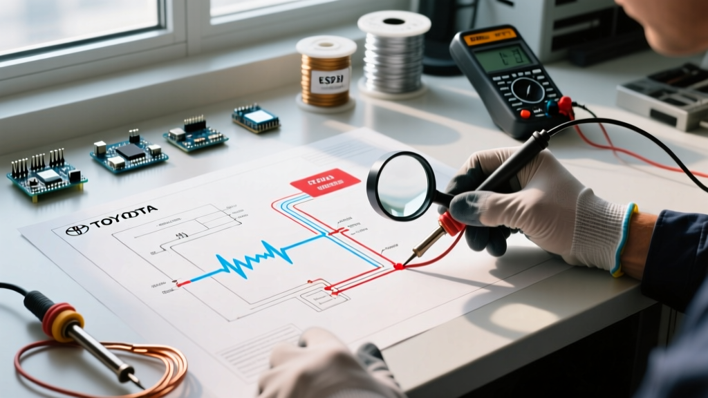
The Toyota Corolla is globally renowned for its mechanical longevity, but modern iterations—particularly the 11th generation (E160/E170, 2014–2019) and 12th generation (E210, 2020–present)—are heavily reliant on complex multiplex communication networks. When electrical gremlins strike, whether it is a parasitic battery drain, a dead infotainment screen, or failing power windows, guessing is not an option. You must consult the official Electrical Wiring Diagram (EWD). Unlike generic aftermarket schematics, Toyota’s EWD format follows a strict, standardized nomenclature that, once decoded, makes tracing circuits highly efficient.
Accessing factory-accurate diagrams is the first step. While third-party repair manuals offer basic overviews, professional technicians rely on Toyota TechInfo for OEM service manuals, including the exact EWDs, connector pinouts, and ground point locations specific to your Corolla's exact VIN and production month.
Decoding Toyota Wire Color Codes
Toyota uses a specific lettering system to denote wire insulation colors on their diagrams. Misinterpreting these can lead to tracing the wrong harness branch. The base color is listed first, followed by the tracer (stripe) color. For example, L-Y indicates a Blue wire with a Yellow tracer.
- B: Black
- W: White
- R: Red
- G: Green
- L: Blue
- Y: Yellow
- BR: Brown
- V: Violet
- O: Orange
- GR: Gray
- SB: Sky Blue
- LG: Light Green
Essential Diagnostic Tools for Corolla Electrical Work
To effectively use a wiring diagram for Toyota Corolla troubleshooting, you need precision tools that prevent damage to delicate terminal pins. Piercing wire insulation with test lights or standard probes is a rookie mistake that invites corrosion and future green-death failures.
- Digital Multimeter (DMM): A high-impedance meter like the Fluke 87V or 88V (automotive) is mandatory. For deeper insights into automotive testing methodologies, refer to the Fluke Automotive Learning Center.
- T-Pin Backprobes: Essential for inserting into the back of sealed Toyota connectors (like the multi-pin ECU plugs) without spreading the female terminal tension rings.
- Oscilloscope or Logic Probe: Required for diagnosing data buses (CAN, LIN, FlexRay) found in 2014+ Corollas. A standard multimeter cannot read the rapid voltage switching of digital data packets.
Step-by-Step Troubleshooting: 11th Gen Power Window LIN Bus
A very common scenario on 2014–2019 Corollas is the failure of passenger-side power windows while the driver's side continues to function. Many DIYers waste hours tearing apart passenger door panels looking for a bad window motor or checking for 12V at the passenger switch. This is a fundamental misunderstanding of modern Toyota wiring.
In these models, the driver’s Master Switch acts as a gateway. It receives your physical button inputs and sends digital commands to the passenger door switches via a LIN (Local Interconnect Network) bus. There are no direct 12V motor-drive wires running from the master switch to the passenger doors.
Tracing the Master Switch Circuit
Using the EWD, locate the Driver Door Control Switch assembly (often labeled as a multi-pin connector, e.g., Connector I4 or similar depending on the exact trim). You will typically find four critical pins for basic operation:
| Pin Function | EWD Label | Expected Voltage (Key ON) | Troubleshooting Insight |
|---|---|---|---|
| Battery Power | B+ / +B | 11.5V – 12.6V (Constant) | Supplies memory and wake-up voltage. If 0V, check the DOOR fuse in the cabin junction block. |
| Ignition Power | IG1 | 11.5V – 14.4V | Powers the main microcontroller. If missing, the integration relay or IG1 fuse is suspect. |
| Ground | GND / E | < 0.05V | Must be tested via voltage drop, not just continuity to chassis. |
| LIN Data Bus | LIN / MPX | ~10V DC Average (Pulsing) | Requires an oscilloscope to view the 0V-12V square wave. A flat 12V or 0V means the master switch microcontroller has crashed or the wire is shorted. |
If the LIN bus wire (usually a single thin wire, often Pink or Violet depending on the harness branch) is broken between the driver's door and the A-pillar boot, all passenger windows will go dead, even though the passenger switches have perfect 12V power and ground. The EWD allows you to trace this single LIN wire through the door hinge rubber boot (a notorious failure point for wire fatigue) without pulling the entire dash.
Tracing CAN Bus Faults at the OBD2 Port
On 12th Generation Corollas (2020+), the vehicle relies heavily on a high-speed CAN (Controller Area Network) bus to allow the Engine Control Module (ECM), Transmission Control Module, and ADAS (Toyota Safety Sense) cameras to communicate. If your check engine light is on but your OBD2 scanner says "Link Error" or "Unable to Connect," the CAN bus is down.
You can use the wiring diagram to diagnose this directly at the Data Link Connector (DLC3 / OBD2 port) located under the driver's dash.
- Locate Pins 6 and 14: Pin 6 is CAN-High (CANH) and Pin 14 is CAN-Low (CANL).
- Resistance Test (Ignition OFF): Set your multimeter to Ohms. Measure between Pin 6 and Pin 14. You should read exactly 60 ohms. This is because the CAN network uses two 120-ohm termination resistors in parallel (one in the ECM, one in the ADAS camera or combination meter).
- Interpret the Data: If you read 120 ohms, one of the termination modules is missing from the network (often due to a disconnected camera or corroded ECU plug). If you read 0 ohms, the CANH and CANL wires are shorted together somewhere in the harness.
Locating Critical Ground Points and Voltage Drop Testing
The most overlooked aspect of using a wiring diagram for Toyota Corolla diagnostics is the ground map. Toyota designates specific ground points with alphanumeric codes. For example, IE designates an Instrument Panel ground, while EA designates an Engine Room ground. The EWD will show you exactly which bolt on the chassis or engine block these wires terminate to.
Expert Warning: Never test a ground by simply setting your multimeter to continuity and probing a random metal dash bracket. Paint, rust, and dissimilar metals can create a diode effect, passing a continuity beep but failing under load. Always perform a Voltage Drop Test.
To perform a voltage drop test on a Corolla ground circuit, set your DMM to DC Volts. Place the red lead on the known-good negative battery terminal and the black lead on the component's ground wire (backprobed). With the circuit active (e.g., radiator fan running), the reading must be less than 0.1V. If you read 0.5V or higher, the ground point listed on your wiring diagram is corroded and requires removal, wire-brushing, and application of dielectric grease.
A Note on SRS (Airbag) Wiring
When tracing diagrams, you will notice the Supplemental Restraint System (SRS) wiring is distinctly colored Yellow. Toyota’s service manuals strictly prohibit backprobing SRS connectors or using standard multimeters to test squib circuits, as the micro-amp current output of some older meters can inadvertently deploy an airbag or pretensioner. Always rely on the SRS diagnostic trouble codes (DTCs) via Techstream rather than manual probing for airbag faults.
Summary
Troubleshooting a Toyota Corolla's electrical system requires moving beyond basic 12V power checks and embracing the logic of multiplex networks. By correctly interpreting the EWD color codes, utilizing backprobes to protect OEM terminals, and understanding the difference between direct power feeds and LIN/CAN data buses, you can accurately isolate faults ranging from a simple blown IG1 fuse to a complex ADAS communication failure. Always pair your physical multimeter readings with the factory wiring diagram to ensure a definitive, lasting repair.