
Installation Planning: Beyond the Basic Ceiling Fan Setup
Upgrading a standard light fixture to a ceiling fan with an integrated light kit is one of the most common residential electrical projects. However, failing to properly interpret the wiring diagram for fan and light configurations before cutting into drywall is the leading cause of abandoned weekend projects and costly electrician callbacks. As an installation planning guide, this article dissects the exact electrical architecture required to independently control a fan motor and light kit from a single wall junction box, ensuring compliance with the latest 2026 National Electrical Code (NEC) standards.
Before purchasing wire or switches, you must determine your existing circuit's capacity and the structural integrity of your ceiling joists. According to the National Fire Protection Association (NFPA), ceiling fans present unique dynamic loads and vibration profiles that standard light fixture boxes cannot safely support.
Critical Safety Warning: Never mount a ceiling fan to a standard nail-on or screw-in light box. Under NEC Article 314.27(C), any ceiling box supporting a fan must be explicitly listed and marked as 'Acceptable for Fan Support.' Failure to do so risks catastrophic structural failure and personal injury.
Decoding the Wiring Diagram for Fan and Light
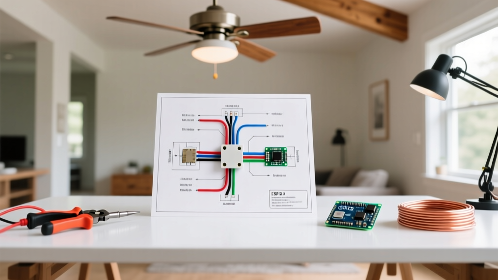
To achieve independent control of the fan and the light from a single wall location, you cannot use a standard 2-conductor cable (14/2 or 12/2). You must utilize a 3-conductor cable to carry two separate switched hot legs. Below is the breakdown of the two primary installation scenarios.
Scenario A: The 3-Wire Independent Control Method (Recommended)
This is the gold standard for modern installations. It requires running a 14/3 or 12/3 NM-B (Romex) cable from the wall switch box to the ceiling fan box.
- Black Wire (Hot 1): Carries switched power from the fan control switch to the fan motor.
- Red Wire (Hot 2): Carries switched power from the dimmer/light switch to the light kit.
- White Wire (Neutral): Completes the circuit for both the motor and the LEDs.
- Bare/Green Wire (Ground): Bonds the metal boxes, switch yokes, and fan canopy to the grounding electrode system.
Scenario B: The 2-Wire Single Switch Method (Retrofit Limitation)
If you are replacing an existing single-pole light fixture and cannot fish a 3-wire cable through finished walls, you are restricted to a 2-wire diagram. In this setup, the single wall switch controls power to the entire unit. The fan and light must then be operated independently using the pull chains on the fan housing or via a smart fan receiver module hidden in the canopy.
Wire Gauge, Breaker Sizing, and Load Matrix
Selecting the correct wire gauge is dictated by the overcurrent protection device (breaker) protecting the circuit. Ceiling fans draw remarkably little current (typically under 1.5 amps), but the circuit must be sized for the total connected load, including the light kit and any other receptacles on the same branch.
| Circuit Breaker | Required NM-B Cable | Max Continuous Wattage (2026 LED Standards) | Typical Application |
|---|---|---|---|
| 15 Amp | 14/3 with Ground | 1,440 Watts | Dedicated bedroom fan/light circuits |
| 20 Amp | 12/3 with Ground | 1,920 Watts | Shared bathroom or multi-fan living areas |
Note: As of 2026, high-efficiency DC motor ceiling fans draw less than 30 watts on high speed, and integrated LED arrays rarely exceed 24 watts. The primary concern is voltage drop over long cable runs rather than thermal overloading.
Step-by-Step Installation Planning Workflow
Follow this precise sequence to ensure a smooth installation day. Budget approximately $85 to $130 for materials (excluding the fan itself) and 4 to 6 hours for a first-time DIYer.
- Verify Power and Map the Circuit: Use a non-contact voltage tester (e.g., Klein Tools NCVT-3) to confirm the breaker is off. Identify if the power source enters at the switch box (line-in) or the ceiling box (line-through). The wiring diagram changes drastically depending on this origin point.
- Upgrade the Ceiling Box: Cut a 4-inch hole in the drywall. Install a retrofit fan-rated brace bar, such as the Carlon B618R-UPC (rated for 70 lbs, approx. $22). Secure the brace bar perpendicular to the joists and screw the PVC box tightly against the drywall.
- Fish the 3-Conductor Cable: Use fiberglass fish tape to pull your 14/3 or 12/3 NM-B cable from the switch box to the ceiling box. Leave 8 inches of slack at both ends.
- Wire the Wall Control: Install a combination fan/light control switch. Connect the line hot to the common terminal, the black load to the fan terminal, and the red load to the light terminal. Bundle all neutrals and grounds in the back of the box.
- Wire the Canopy: At the ceiling, connect the black wire to the fan motor lead, the red wire to the light kit lead, the white to the combined neutral pigtail, and the bare wire to the fan's green ground screw.
Common Failure Modes & Troubleshooting
Even with a perfect wiring diagram for fan and light setups, specific edge cases frequently cause post-installation headaches. Understanding these failure modes is a hallmark of expert-level planning.
1. LED Flickering and Ghosting
The Problem: The light kit flickers when dimmed, or glows faintly when turned off.
The Cause: Using an incompatible dimmer or a smart switch that bleeds a small amount of current through the neutral to power its internal Wi-Fi radio.
The Fix: Ensure you are using a dimmer specifically rated for low-wattage LEDs, such as the Lutron Diva LED+ (DVCL-153P). If using a smart switch, install a Lutron LUT-MLC bypass capacitor across the light kit's hot and neutral wires to absorb the bleed current.
2. Motor Humming and Overheating
The Problem: The fan emits a loud 60Hz hum and runs hot.
The Cause: The installer wired the fan motor's hot lead to the dimmer switch instead of the fan speed control.
The Fix: Never use a standard lighting dimmer to control an AC fan motor. The chopped sine wave destroys the motor's capacitors and creates a severe fire hazard. Always use a dedicated fan speed control (e.g., Leviton RZS10-1L).
3. Tripped AFCI Breakers
The Problem: The bedroom AFCI breaker trips immediately when the fan is turned on.
The Cause: Shared neutrals. If the 14/3 cable's neutral is accidentally mixed with a neutral from a different circuit in the switch box, the AFCI will detect an imbalance and trip.
The Fix: Keep all neutrals strictly isolated by circuit. Use wire markers to label the fan circuit's neutral before pushing wires into the back of the box.
Recommended Hardware for 2026 Installations
To ensure longevity and compliance, source the following specific components for your project:
- Wall Control: Lutron MACL-LFQH Maestro LED+ Fan Control & Light Dimmer (Approx. $48). Features a built-in microprocessor that prevents motor humming and optimizes LED dimming curves.
- Ceiling Box: Raco 937 Retrofit Fan Box (Approx. $18). Features a heavy-duty steel brace bar that expands up to 24 inches, ideal for older homes with irregular joist spacing.
- Wire Connectors: Ideal Industries In-Sure Push-In Connectors (Lever-Nut equivalent). For ceiling canopy work where space is tight and overhead wire nut twisting causes arm fatigue, push-in connectors provide a secure, UL-listed connection in seconds.
Frequently Asked Questions
Can I use a 14/2 wire if I only want the wall switch to control the light, and use pull chains for the fan?
Yes. If you are willing to rely on pull chains or a remote control for the fan motor, a standard 14/2 NM-B cable is sufficient. The wall switch will simply act as a master disconnect for the entire unit's hot leg.
Do I need to upgrade my electrical panel for a new ceiling fan?
Almost never. A modern DC-motor ceiling fan with an LED light kit draws less than 0.5 amps total. Unless your existing circuit is already overloaded with high-draw appliances (like space heaters or window AC units), adding a fan will not impact your panel's capacity.
For more information on safe home electrical upgrades and load calculations, refer to the U.S. Consumer Product Safety Commission's home electrical safety guides. Additionally, when selecting your fixture, always look for the ENERGY STAR certification for ceiling fans to guarantee airflow efficiency and motor longevity.