
Decoding the Travel Trailer Electrical Architecture
Understanding the wiring diagram for a travel trailer requires recognizing that you are actually dealing with three distinct but interconnected electrical systems: the 12V DC tow vehicle chassis circuit, the 120V AC shore power system, and the 12V DC house battery network. In 2026, with the mass adoption of LiFePO4 lithium batteries and high-efficiency DC-DC chargers, factory wiring diagrams are frequently modified by owners to handle increased current loads. This comprehensive reference guide breaks down the exact pinouts, wire gauges, power center routing, and common failure modes inherent in modern travel trailers.
The 7-Way RV Blade Connector: Tow Vehicle to Trailer
The 7-way Bargman-style blade connector is the lifeline between your tow vehicle and the trailer's chassis systems. It handles lighting, electric brakes, and auxiliary 12V power. Below is the industry-standard pinout mapping for the trailer-side female receptacle (looking at the face of the connector).
| Pin Position | Function | Standard Wire Color | Recommended Gauge (2026 Std) |
|---|---|---|---|
| Pin 1 (Top Left) | Left Turn / Stop | Yellow | 14 AWG |
| Pin 2 (Top Right) | Electric Brakes | Blue | 10 AWG (Upgrade from 12) |
| Pin 3 (Bottom Left) | Ground (Chassis) | White | 10 AWG or 8 AWG |
| Pin 4 (Bottom Right) | Auxiliary 12V Power | Black or Red | 10 AWG or 8 AWG |
| Pin 5 (Center Left) | Right Turn / Stop | Green | 14 AWG |
| Pin 6 (Center Right) | Tail / Running Lights | Brown | 14 AWG |
| Pin 7 (Center Bottom) | Center Aux / Reverse | Purple | 14 AWG |
Critical Failure Mode: The Electric Brake Voltage Drop
Many factory wiring diagrams utilize 12 AWG wire for the blue electric brake circuit (Pin 2). On a 30-foot travel trailer, pushing 15+ amps to four 10-inch electric brake assemblies through 12 AWG wire results in a severe voltage drop. By the time the current reaches the rear axle brakes, voltage can drop below 10V, causing uneven braking and premature magnet wear. Expert Fix: When tracing or repairing your trailer's wiring diagram, replace the blue brake feed wire with 10 AWG copper, and ensure your tow vehicle's brake controller (e.g., Tekonsha Prodigy P3 or Curt Spectrum) is also wired with 10 AWG back to the battery.
120V AC Shore Power and the Power Converter
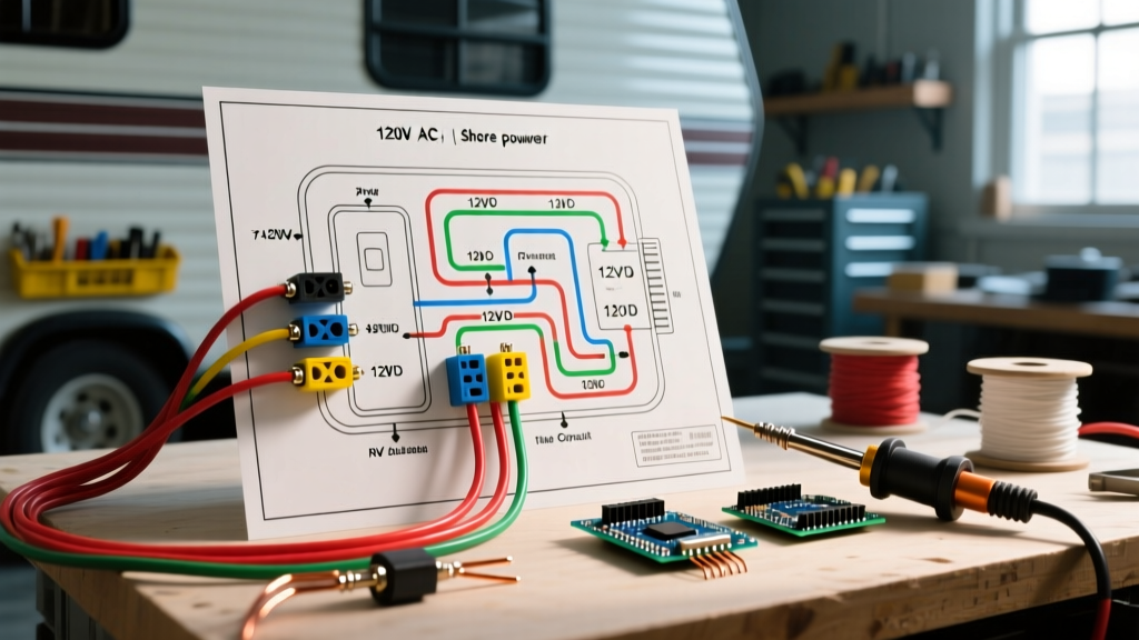
When plugged into a campground pedestal, your travel trailer relies on either a 30-amp (TT-30R, 120V) or 50-amp (14-50R, 120/240V) shore power connection. The 120V AC wiring diagram routes power from the main shore cord into the RV's Power Distribution Center (PDC), commonly manufactured by WFCO or Progressive Dynamics.
Inside the Power Distribution Center (PDC)
The PDC houses two distinct sections: the AC breaker panel and the DC fuse board, bridged by the power converter.
- Main AC Breaker: Typically a 30A or 50A double-pole breaker that protects the entire rig from shore pedestal surges.
- Branch AC Breakers: 15A or 20A breakers dedicated to specific loads (e.g., 20A for the microwave, 15A for the GFI bathroom outlet, 15A for the rooftop AC unit).
- The Power Converter: This device steps down 120V AC to 13.6V DC to power the house loads and charge the battery bank. A standard WFCO WF-8955-PEC (55-Amp, ~$160) is common, but for 2026 lithium upgrades, a Progressive Dynamics PD9260LIV (~$260) with a dedicated LiFePO4 charging profile is required to prevent BMS overvoltage shutdowns.
Code Compliance Note: According to National Fire Protection Association (NFPA) Article 551 governing Recreational Vehicles, all 120V AC metallic enclosures, including the PDC chassis and appliance frames, must be bonded to the main equipment grounding busbar. Never use the DC negative busbar as an AC ground.
12V DC House Wiring and Lithium Integration
The 12V DC house wiring diagram originates at the battery bank, passes through a main Class-T fuse (typically 150A to 300A), and terminates at the negative and positive busbars before feeding into the PDC's DC fuse panel. Modern travel trailers are increasingly abandoning dual 6V AGM golf cart batteries in favor of 12V 200Ah LiFePO4 drop-in replacements (such as the Renogy Smart Lithium or Victron Smart Lithium).
Upgrading for DC-DC Charging
If your wiring diagram includes a DC-DC charger to charge the house bank from the tow vehicle's alternator via the 7-way Pin 4 (Auxiliary), you must upgrade the wiring. A Victron Orion-Tr Smart 12/12-30 draws up to 32A from the tow vehicle. Running 32A through 25 feet of factory 12 AWG wire will cause the Victron's input undervoltage protection to trip. You must rewire Pin 4 with 8 AWG wire directly from the tow vehicle's alternator post to the trailer's DC-DC input.
Solar and Inverter Wiring Additions
Most modern travel trailer wiring diagrams now account for roof solar and AC inverters. Here is the proper signal and power flow for these additions:
- Solar Array to Controller: Roof panels wired in series (to increase voltage and reduce wire gauge) down to an MPPT charge controller (e.g., Victron SmartSolar 100/30) mounted within 5 feet of the battery busbars.
- Controller to Busbar: Heavy gauge wire (6 AWG or 4 AWG) with an inline ANL fuse sized 125% above the max controller output.
- Inverter Sourcing: High-wattage inverters (e.g., Victron MultiPlus 12/3000) draw massive DC current (up to 250A). They must be wired directly to the battery busbars using 2/0 AWG welding cable, never through the PDC's standard DC fuse panel.
Wire Gauge and Overcurrent Protection Matrix
Use the following reference matrix when modifying or repairing your travel trailer's wiring diagram to ensure compliance with Recreation Vehicle Industry Association (RVIA) standards and to prevent thermal events.
| Wire Gauge (Copper) | Max Continuous Amps | Max Run Length (12V DC, 3% Drop) | Required Fuse/Breaker Size |
|---|---|---|---|
| 14 AWG | 15A | ~8 feet | 15A |
| 12 AWG | 20A | ~12 feet | 20A |
| 10 AWG | 30A | ~18 feet | 30A |
| 8 AWG | 40A | ~25 feet | 40A - 50A |
| 6 AWG | 55A | ~35 feet | 60A |
| 4 AWG | 70A | ~50 feet | 80A |
| 2/0 AWG | 195A | ~10+ feet (Inverter runs) | 250A Class-T |
Troubleshooting Common Wiring Diagram Faults
The 'Ghost' Running Light Issue
If your trailer's running lights glow dimly when only the brake pedal is pressed, or your interior 12V lights flicker when the turn signal activates, you have a compromised chassis ground. The white wire (Pin 3) on the 7-way connector is often grounded to the trailer tongue via a self-tapping screw. Over time, oxidation builds up under the screw head. The current seeks an alternate path to ground, backfeeding through the brown (tail light) wire. Solution: Remove the self-tapper, clean the metal to bare steel, and reinstall using a dedicated grounding bolt with a stainless steel star washer to bite through the paint and rust.
Converter Overheating and Fan Noise
If your WFCO or Progressive Dynamics converter fan runs constantly and the unit is hot to the touch, check the DC wiring diagram at the fuse panel. A loose 30A or 40A reverse-polarity fuse creates high resistance, forcing the converter to work harder to push current. Tighten all set-screws on the DC busbars and apply a torque of 20 in-lbs to prevent thermal creep.
Summary
Mastering the wiring diagram for a travel trailer is essential for safe towing, efficient off-grid camping, and preventing electrical fires. By upgrading critical choke-points—such as the 7-way brake wire to 10 AWG, installing lithium-compatible converters, and ensuring pristine chassis grounds—you ensure your rig's electrical architecture is reliable for the long haul. Always consult Victron Energy's technical whitepapers when integrating complex DC-DC and solar routing to verify BMS communication protocols and wire sizing.