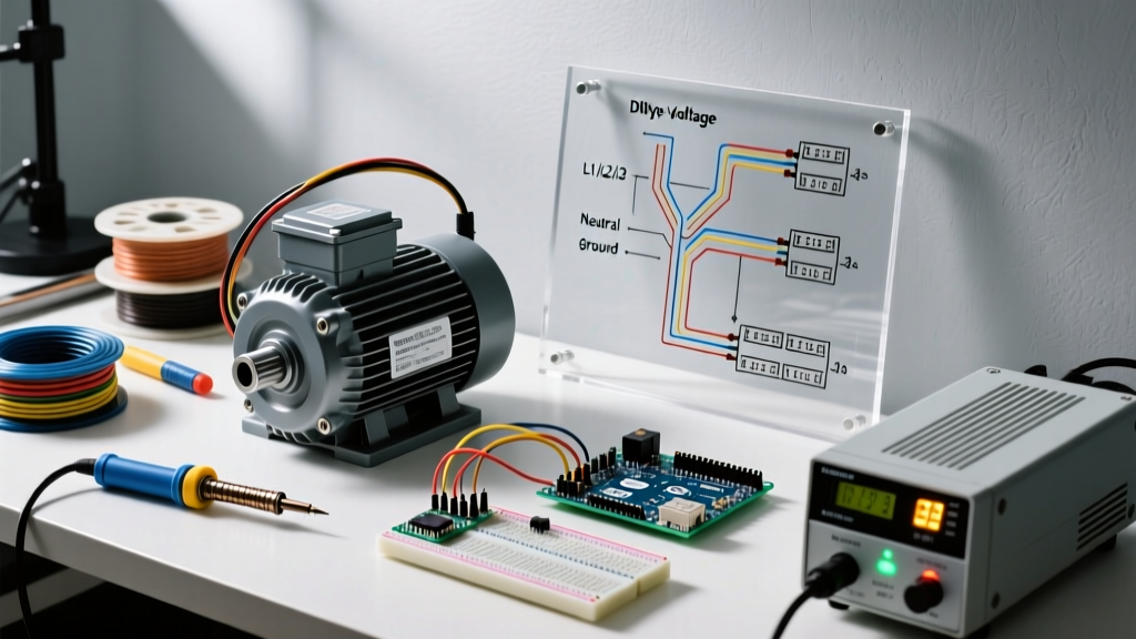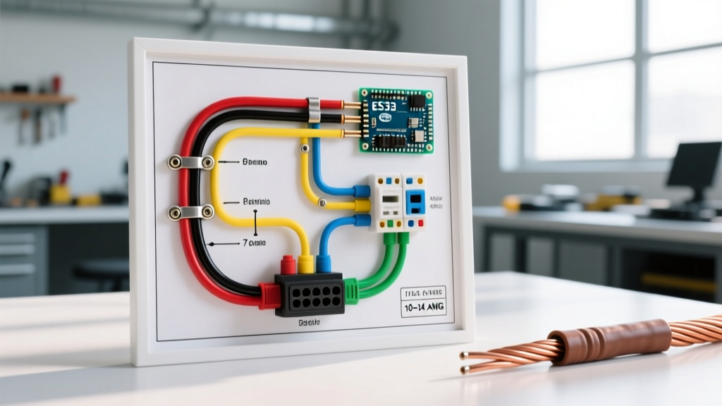

The Critical Role of Panel & Breaker Protection in Trailer Braking
When enthusiasts and professionals search for a wiring diagram for electric brakes on a trailer, the focus is almost entirely on the 7-way RV blade connector and the brake magnets at the wheels. However, as any seasoned mobile electrician knows, the true reliability of a 12V DC trailer braking system is determined at the source: the tow vehicle's breaker panel, wire gauge selection, and circuit protection architecture. In 2026, with modern half-ton trucks pushing towing capacities past 13,000 lbs and gooseneck trailers utilizing triple-axle setups, the electrical draw from electric brakes can easily exceed 35 amps under heavy panic-braking scenarios.
According to the National Highway Traffic Safety Administration (NHTSA), electrical failures and trailer disconnects remain a leading cause of highway towing incidents. If your circuit breaker is undersized, it will trip during a hard stop, leaving you with zero trailer braking power. If your wire gauge is too thin, voltage drop will starve the brake magnets, resulting in a spongy, unresponsive feel. This guide bridges the gap between the standard wiring schematic and the heavy-duty panel requirements necessary for safe, SAE-compliant towing.
Core Wiring Diagram Mapping: Battery to Brake Magnets
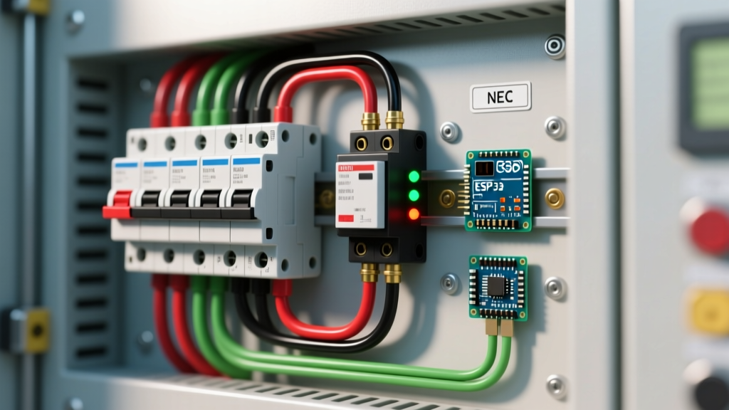
Before cutting and crimping, you must understand the power flow. Unlike standard automotive lighting circuits which are fused at the fuse box, the electric brake controller requires a dedicated, high-amperage DC circuit breaker mounted as close to the vehicle's battery positive terminal as possible.
The Power Path Sequence
- Source: Tow Vehicle 12V Battery Positive Terminal.
- Protection: 30A, 40A, or 50A Auto-Reset DC Circuit Breaker (e.g., Bussmann 1020-Series).
- Controller Input: Black wire on the brake controller (e.g., Tekonsha Prodigy P3, Model 90195).
- Controller Output: Blue wire routed to the 7-Way RV Blade (Pin 2 - Electric Brakes).
- Trailer Junction Box: Blue wire splices to the individual left and right brake magnet wires (typically 10 AWG or 12 AWG).
- Ground Return: Brake magnets ground to the trailer chassis; trailer chassis grounds to the tow vehicle via the 7-Way Blade (Pin 1 - White Ground Wire).
Expert Warning: Never route the brake controller's main power wire through the vehicle's interior firewall without a dedicated grommet, and never rely on the factory 12V auxiliary fuse block for the primary brake power feed. The high transient current spikes during ABS cycling can melt standard ATC/ATO fuse block traces.
Breaker Sizing & Wire Gauge Selection Matrix
The SAE J2807 towing standard dictates rigorous performance metrics for trailer braking, but it assumes the electrical system can deliver full voltage to the magnets. Selecting the correct wire gauge and breaker pairing is non-negotiable. The table below provides exact specifications based on axle count and total brake magnet draw.
| Trailer Configuration | Total Brakes | Max Current Draw | Required Wire Gauge (SAE J1128 GXL) | Circuit Breaker Rating | Max One-Way Run Length |
|---|---|---|---|---|---|
| Single Axle (Light Duty) | 2 | 10A - 12A | 12 AWG | 20A Bussmann 1020 | 15 Feet |
| Tandem Axle (Standard RV) | 4 | 20A - 24A | 10 AWG | 30A Bussmann 1020 | 25 Feet |
| Triple Axle (Heavy/Gooseneck) | 6 | 30A - 36A | 8 AWG | 40A Bussmann 1020 | 30 Feet |
| Quad Axle (Massive Hauler) | 8 | 40A - 48A | 6 AWG | 50A Littelfuse MEGA | 35 Feet |
Note: Always use SAE J1128 GXL (Cross-linked polyethylene) wire rather than standard PVC THHN. GXL wire withstands the high undercarriage temperatures and abrasion inherent to truck and trailer routing, and its thinner insulation allows for easier pulling through tight frame channels.
Step-by-Step Panel & Breaker Installation Guide
Proper installation of the DC breaker and controller wiring requires precision. Here is the professional workflow for hardwiring an aftermarket controller like the Curt Discovery (Model 51120) or the Tekonsha Prodigy P3.
- Disconnect the Battery: Always isolate the negative terminal first to prevent dead-shorting the wrench against the chassis while working on the positive side.
- Mount the Circuit Breaker: Secure the Bussmann 1020-Series breaker to the inner fender well or firewall. It must be within 18 inches of the battery positive post. Use stainless steel hardware and apply a torque of 8-10 Nm to the 5/16' ring terminal nuts to prevent micro-arcing.
- Run the Primary Feed (Black Wire): Route the 10 AWG or 8 AWG GXL wire from the battery-side stud of the breaker, through a heavy-duty rubber firewall grommet, directly to the brake controller's black pigtail.
- Crimp, Don't Solder: Use a high-quality ratcheting crimper (like the Knipex 13 82 6) with heat-shrink ring terminals. Soldering DC automotive connections is discouraged as the solder can wick under the insulation, creating a brittle stress point that snaps under chassis vibration.
- Route the Output (Blue Wire): Run the blue output wire from the controller back to the 7-way RV socket. Keep this wire separated from CAN-bus or data lines to prevent electromagnetic interference (EMI) which can cause erratic brake controller behavior.
- Apply Dielectric Protection: Coat all ring terminals and the 7-way blade pins with a lithium-based dielectric grease (e.g., Permatex Part #22058) to prevent galvanic corrosion, especially in winter environments where road salt is prevalent.
Integrating the Breakaway System: The Secondary Safety Net
A complete wiring diagram for electric brakes on a trailer must include the breakaway system. If the trailer physically detaches from the hitch, the breakaway lanyard pulls a pin from a switch, instantly applying 12V directly to the brake magnets to lock the trailer wheels.
The breakaway system requires its own dedicated power source and charging circuit:
- Breakaway Battery: Typically a 12V 5Ah Sealed Lead Acid (SLA) battery mounted in a weatherproof box on the trailer tongue.
- Charging Circuit: The tow vehicle's 7-way Pin 4 (12V Auxiliary/Accessory) provides a constant 12V charge to the breakaway battery while driving. This line must be protected by a 20A inline ATC fuse or a 20A DC breaker at the tow vehicle's panel.
- The Switch Logic: The breakaway switch is wired in parallel with the brake controller's blue output wire. When triggered, it bypasses the controller and feeds full battery voltage from the breakaway battery directly to the magnets, ensuring maximum clamping force regardless of the tow vehicle's status.
Advanced Troubleshooting: Voltage Drop and Edge Cases
Even with a perfect wiring diagram, real-world conditions introduce variables that can compromise braking performance. Use a high-impedance digital multimeter (such as the Fluke 87V) to diagnose these specific failure modes.
1. The 'Spongy Brake' Voltage Drop Test
Electric brake magnets require a minimum of 11.5V to achieve full magnetic saturation. If you are experiencing weak braking, perform a loaded voltage drop test:
- Set the brake controller to maximum manual output (100%).
- Measure voltage at the controller's blue output wire. It should read ~12.4V.
- Measure voltage at the trailer's junction box (where the blue wire splits to the axles).
- The Diagnosis: If the voltage at the junction box is below 11.0V, you have excessive resistance. This is almost always caused by undersized wire, a corroded 7-way blade, or a poor chassis ground. Clean the 7-way pins with a fiberglass scratch pen and re-test.
2. False Triggering from LED Taillight Adapters
Many modern trailers use LED lighting, which draws significantly less current than incandescent bulbs. Some older or poorly designed brake controllers use the taillight circuit (Pin 3 on the 7-way) to sense when the vehicle is braking. Because LEDs draw so little current, the controller may fail to register the brake pedal application, or conversely, phantom voltage from LED driver modules can cause the trailer brakes to lock up randomly. The Fix: Install a dedicated stoplight switch wire directly from the tow vehicle's brake pedal switch to the controller's red input wire, bypassing the taillight sensing logic entirely.
3. Thermal Breaker Fatigue
If you are towing down a steep mountain grade (e.g., the Eisenhower Tunnel on I-70) and your trailer brakes suddenly stop working, only to return 10 minutes later, your DC circuit breaker is experiencing thermal fatigue. Standard auto-reset thermal breakers will trip early if ambient under-hood temperatures exceed 140°F (60°C). For heavy mountain towing, upgrade to a magnetic-hydraulic breaker or increase your wire gauge and breaker rating by one tier (e.g., move from 10 AWG/30A to 8 AWG/40A) to provide a larger thermal buffer.
Final Safety and Compliance Checks
Before taking your rig onto the highway, perform a static draw test. Disconnect the trailer and use an ammeter on the breakaway charging circuit to ensure it is not drawing more than 0.5A (the float charge rate for a 5Ah SLA battery). Verify that all chassis grounds are sanded down to bare, unpainted metal and secured with star washers. By treating the panel and breaker side of the equation with the same rigor as the mechanical brake components, you ensure that your wiring diagram translates into real-world stopping power, keeping your cargo and fellow drivers safe on the road.