
Decoding the Three Phase Electric Motor Wiring Diagram
Wiring a three phase electric motor goes far beyond simply connecting T1, T2, and T3 to a power source. A proper installation requires strict adherence to thermal limits, voltage drop calculations, and National Electrical Code (NEC) mandates. Whether you are commissioning a 1 HP coolant pump or a 50 HP HVAC compressor, understanding the intersection of wire gauge selection, phase color coding, and internal motor configurations (Wye vs. Delta) is critical for operational longevity and safety.
In this comprehensive guide, we break down the exact parameters needed to execute a flawless three phase electric motor wiring diagram, referencing the latest NEC Article 430 standards and NEMA MG-1 specifications for industrial and commercial applications.
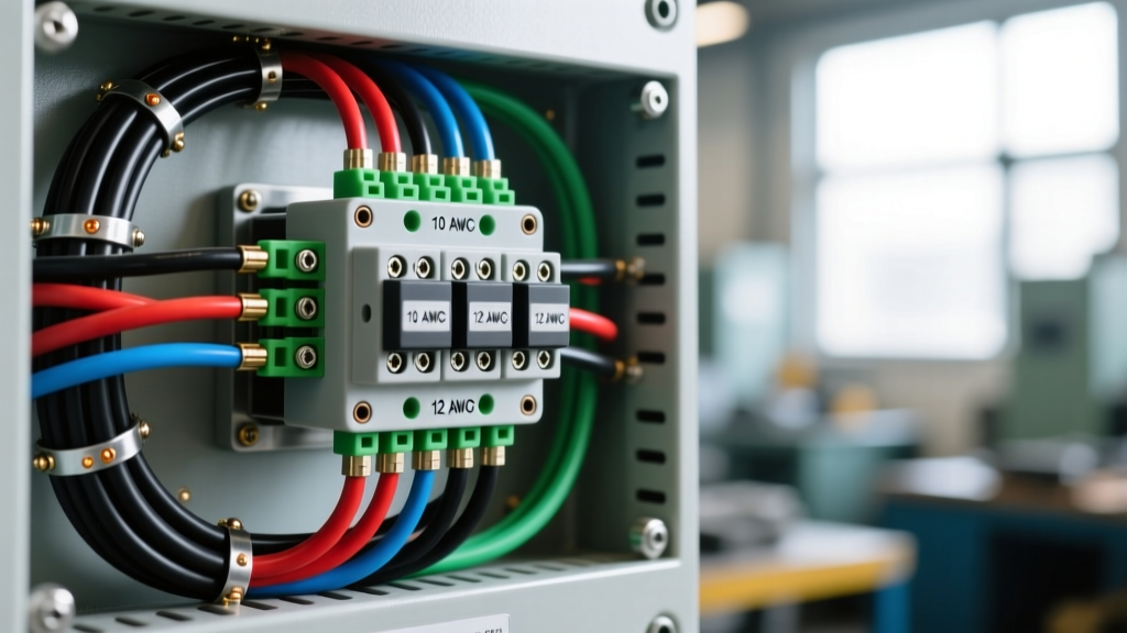
NEC-Compliant Wire Gauge Selection for 3-Phase Motors
The most common failure point in motor installations is undersized conductors. According to NEC Article 430.22, conductors supplying a single continuous duty motor must have an ampacity of not less than 125% of the motor's Full Load Current (FLC) as listed in NEC Tables 430.247 through 430.250, not the nameplate amperage.
Furthermore, NEC 110.14(C) dictates that termination temperature ratings must be respected. Even if you use 90°C THHN wire, the ampacity must be calculated using the 75°C column of NEC Table 310.16 for terminations rated at 75°C, which is standard for most industrial motor starters and disconnects.
3-Phase Motor Wire Sizing Matrix (THHN Copper, 75°C Column)
| Motor HP | 230V FLC | 460V FLC | Min Ampacity (125%) | Recommended AWG (230V) | Recommended AWG (460V) |
|---|---|---|---|---|---|
| 3 HP | 9.6 A | 4.8 A | 12.0 A / 6.0 A | 12 AWG | 14 AWG |
| 7.5 HP | 22 A | 11 A | 27.5 A / 13.7 A | 8 AWG | 12 AWG |
| 15 HP | 42 A | 21 A | 52.5 A / 26.2 A | 4 AWG | 8 AWG |
| 30 HP | 80 A | 40 A | 100 A / 50 A | 1 AWG | 4 AWG |
| 50 HP | 130 A | 65 A | 162.5 A / 81.2 A | 2/0 AWG | 2 AWG |
Note: Always verify the specific FLC on the motor nameplate, as high-efficiency premium motors (IE3/IE4) may draw slightly less current than standard NEC tables suggest.
3-Phase Color Code Standards: US vs. IEC
Misidentifying phase conductors can lead to catastrophic phase-reversal issues, causing motors to run backward and potentially destroying driven equipment like scroll compressors or centrifugal pumps. The color coding depends heavily on your regional standards and voltage class.
United States (NEC / NEMA Standards)
- 208V / 240V 3-Phase: Black (L1), Red (L2), Blue (L3).
- 480V / 600V 3-Phase: Brown (L1), Orange (L2), Yellow (L3).
- High-Leg Delta (240V): Phase A (Black), Phase B (Orange - High Leg / Wild Leg), Phase C (Red). The high leg must always be identified by orange outer finish or tagging per NEC 208.7(A).
- Ground: Green, Green with Yellow Stripe, or Bare Copper.
International (IEC 60446 / EN 60204 Standards)
- Standard 3-Phase (400V/480V): Brown (L1), Black (L2), Grey (L3).
- Neutral (if applicable): Blue.
- Ground: Green/Yellow bi-color stripe.
Expert Tip: Never rely solely on insulation color in older facilities. Always verify voltage and phase rotation using a calibrated meter like the Fluke 9040 Phase Rotation Indicator before making final terminations. Legacy wiring often violates modern color codes.
Navigating 9-Lead Dual Voltage Motor Configurations
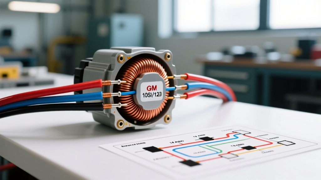
Most industrial three phase electric motors (ranging from 1 HP to 50 HP) are dual-voltage, featuring 9 external leads (T1 through T9). These can be wired in either Wye (Star) or Delta configurations depending on the internal winding design. Always check the nameplate diagram.
Wye (Star) Configuration Wiring Flow
Used commonly for high starting torque applications and reduced voltage starting.
- Low Voltage (230V): Group and connect leads 1 & 7 to L1; 2 & 8 to L2; 3 & 9 to L3. Tie leads 4, 5, and 6 together to form the neutral/star point (do not connect to supply neutral).
- High Voltage (460V): Group and connect leads 4, 7, and 8 together; 5, 8, and 9 together (Wait, standard Wye HV: Tie 4-7, 5-8, 6-9 together. Connect L1 to 1, L2 to 2, L3 to 3).
Correction for High Voltage Wye: Tie 4 & 7 together, 5 & 8 together, 6 & 9 together. Apply L1 to T1, L2 to T2, L3 to T3.
Delta Configuration Wiring Flow
Standard for most general-purpose HVAC and pump applications.
- Low Voltage (230V): Tie 1, 6, and 7 together (L1). Tie 2, 4, and 8 together (L2). Tie 3, 5, and 9 together (L3).
- High Voltage (460V): Tie 1 & 9 together (L1). Tie 2 & 7 together (L2). Tie 3 & 8 together (L3). Tie 4, 5, and 6 together independently.
Real-World Failure Modes and Troubleshooting
Even with a perfect three phase electric motor wiring diagram on paper, physical installation errors cause the majority of premature stator burnouts. According to NEMA MG-1 guidelines, the following edge cases must be mitigated:
1. Single-Phasing
If one phase is lost while the motor is running, the remaining two phases will draw approximately 173% of the normal full load current to maintain torque. Without proper overload protection, the windings will overheat and melt within minutes. Solution: Install a solid-state phase monitor relay (e.g., Macromatic SE-700 series) set to trip on >2% voltage unbalance or phase loss.
2. Voltage Unbalance
A mere 1% voltage unbalance across the three phases causes a 6% to 10% temperature rise in the motor windings, drastically shortening insulation life. Always measure phase-to-phase voltage at the motor terminals under load, not just at the MCC (Motor Control Center).
3. Loose Terminations and Micro-Arcing
Vibration from the motor and driven load can loosen mechanical lugs over time. This increases contact resistance, leading to localized heating and eventual phase loss.
Expert Termination Protocols and Torque Specifications
To ensure compliance with OSHA electrical safety standards and prevent thermal failures at the terminal block, follow these strict termination protocols:
- Wire Preparation: Use ratcheting wire strippers (like the Klein Tools 11055) to avoid nicking the copper conductor. Nicks create stress risers that lead to strand breakage under vibration.
- Oxidation Inhibition: Apply a thin layer of Noalox or equivalent anti-oxidant compound to aluminum conductors. Copper conductors in dry indoor environments generally do not require it, but it is mandatory for damp or outdoor locations.
- Precise Torque: Never 'gut-tighten' motor lugs. Use a calibrated torque screwdriver. For standard 10-32 terminal screws on fractional HP motors, the target torque is typically 20 to 25 in-lbs. For larger mechanical lugs on 4 AWG wire, torque specs usually range from 40 to 50 in-lbs (always verify the manufacturer's stamp on the lug).
- Strain Relief: Ensure the cable gland or conduit connector provides adequate strain relief so that no mechanical pull is transferred to the internal motor winding leads.
Final Commissioning Checklist
Before energizing the circuit, verify the following:
- Megger test the motor windings to ground (expect >100 Megohms for new motors).
- Verify phase rotation matches the driven equipment requirement using a phase meter.
- Confirm overload heater sizing or solid-state overload parameters are set exactly to the motor nameplate FLA, not the NEC table FLC.
- Bump the motor (energize for <1 second) to verify correct rotation direction before fully coupling the load.
By treating the three phase electric motor wiring diagram as a comprehensive system of gauge calculations, color identification, and precision terminations, you eliminate the variables that lead to catastrophic downtime. Always prioritize NEC compliance and NEMA standards over legacy 'rules of thumb' to ensure your 2026 installations remain robust and efficient for decades.