
The Shift from Analog to CAN-Bus: Why Generic Diagrams Fail
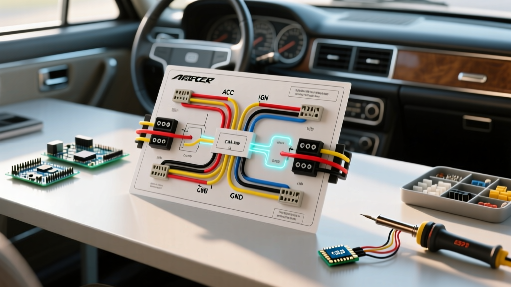
If you are upgrading a modern vehicle's audio system, relying on a generic, one-size-fits-all schematic is a fast track to blown fuses, parasitic battery drains, or triggering a check engine light. In the current 2026 automotive landscape, over 85% of new vehicles utilize multiplexed CAN-bus (Controller Area Network) systems rather than traditional analog 12V switched wires. When you pull up a wiring diagram for aftermarket stereo installations, you are actually looking at a translation map between the standardized head unit and the highly proprietary OEM vehicle harness.
According to the Mobile Electronics Certification Program (MECP), misinterpreting OEM data lines as standard 12V power sources is the number one cause of catastrophic head unit failure in modern installations. This guide breaks down how to read, verify, and execute vehicle-specific wiring diagrams, ensuring your upgrade integrates flawlessly with your car's computer network.
Decoding the EIA/CTA Standard vs. OEM Harnesses
Every valid wiring diagram for aftermarket stereo setups is divided into two distinct halves. The left side represents the aftermarket head unit, which strictly follows the Consumer Technology Association (CTA) color-code standard. The right side represents the vehicle's factory harness, which varies wildly by manufacturer, model year, and trim level.
| CTA Wire Color | Function | Common OEM Equivalent (Varies by Vehicle) | Critical Installation Note |
|---|---|---|---|
| Yellow | Constant 12V+ (Memory) | White/Red, Yellow/Green, or CAN-bus Data | Must have voltage when the car is OFF. Powers memory and standby. |
| Red | Switched 12V+ (Accessory) | White/Green, Purple, or Data-Triggered | Must turn OFF when the key is removed to prevent battery drain. |
| Black | Chassis Ground | Black, Black/White, or Bare Copper | Never ground to a painted surface or plastic trim screw. |
| Blue/White | Amplifier Turn-On | Blue, Pink, or Data-Triggered via Interface | Provides a 300mA max trigger signal. Do not use to power motors. |
Vehicle-Specific Scenarios: Ford, Honda, and Toyota
To truly understand how to apply a wiring diagram, we must look at specific vehicle platforms. Here is how the diagram changes based on the OEM architecture.
1. Ford F-150 (2015–2026): The CAN-Bus and RAP Challenge
In modern F-150s, there is no physical 'accessory' 12V wire at the radio cavity. The factory SYNC module receives a CAN-bus wake-up signal and retains power until the driver's door is opened (Retained Accessory Power, or RAP). If your wiring diagram shows a standard red accessory wire, you cannot simply tap the cigarette lighter fuse; doing so will bypass the RAP feature and may cause a parasitic drain.
The Fix: You must use a CAN-bus interface module like the iDatalink Maestro RR2 (retailing around $199). The Maestro intercepts the vehicle's high-speed CAN network and generates a clean 12V+ switched output for the aftermarket stereo's red wire, while also retaining steering wheel controls and climate data on the new screen.
2. Honda Civic (2016–2021): Differential Audio and Ground Loops
Honda and Acura frequently use differential (balanced) audio signals from the factory head unit to the factory amplifier to reduce alternator whine. If your wiring diagram indicates standard single-ended RCA pre-outs, and you use a cheap $15 line-out converter (LOC), you will introduce severe ground-loop noise into your aftermarket amplifiers.
The Fix: You need a differential-to-single-ended converter, such as the Axxess HD-CB01 ($45). The wiring diagram for this specific harness requires you to tap both the positive and negative audio signal wires for each channel before feeding them into your DSP or aftermarket amplifiers.
3. Toyota Tacoma with JBL: Bypassing the Factory Amplifier
When upgrading a JBL-equipped Tacoma, the factory wiring diagram shows low-level (speaker wire) outputs entering the factory amp, and amplified signals leaving it. If you bypass the amp but don't satisfy the CAN-bus network, the vehicle will throw a U-code (communication fault) and may disable other infotainment features.
The Fix: Utilize a bypass harness like the PAC TO2-AMP ($60). This harness plugs inline, tricks the CAN-bus into thinking the JBL amp is still present, and provides clean low-level RCA outputs for your new aftermarket head unit.
Step-by-Step: Verifying the Diagram with a Multimeter
Never trust a printed wiring diagram blindly. Factory wire colors can change mid-production year. Always verify the diagram's claims using a digital multimeter (DMM).
- Verify Constant 12V (Yellow): Set your DMM to DC Voltage. Probe the suspected constant wire against a known bare metal ground. It should read 12.2V–12.6V with the vehicle completely OFF and the key removed.
- Verify Switched 12V (Red): Probe the suspected accessory wire. It should read 0V with the key OFF. Turn the key to the 'ACC' or 'RUN' position; the meter should jump to 12.2V–12.6V. Turn the key OFF, and it must drop back to 0V.
- Verify Ground (Black): Set your DMM to Continuity (the beep setting). Place one probe on the suspected ground wire and the other on a bare metal chassis bolt. A continuous beep confirms a solid ground path. If using an ohmmeter, resistance should be below 0.5 ohms.
- Identify Data Wires (CAN-H / CAN-L): If you see twisted pairs of wires (often Green/White and Green/Brown in Ford, or Pink/White and Pink in GM), do not probe them with a standard test light. Use a DMM on AC Voltage; CAN-bus lines typically fluctuate between 1.5V and 3.5V. Splicing into these with a T-tap will corrupt the vehicle's network.
Troubleshooting Matrix: Common Wiring Diagram Misreads
| Symptom | Probable Diagram Misinterpretation | Corrective Action |
|---|---|---|
| Head unit turns on, but loses presets/clock every time the car is turned off. | Swapped Yellow (Constant) and Red (Switched) wires. | Swap the connections at the harness adapter. Yellow must have constant power to maintain volatile memory. |
| External amplifier stays on after the car is turned off, draining the battery. | Tapped the Blue (Power Antenna) wire instead of Blue/White (Amp Turn-On). | The Power Antenna wire drops to 0V when the radio is tuned away from the FM/AM band. Rewire to the Blue/White remote turn-on lead. |
| Alternator whine that pitches up and down with engine RPM. | Grounding the head unit and amplifiers to different chassis points, creating a ground loop. | Ensure all audio components share a single, clean, bare-metal grounding point, or use a ground loop isolator on the RCA cables. |
| Steering wheel controls (SWC) respond erratically or not at all. | Using a resistor-based SWC diagram on a CAN-bus vehicle. | Upgrade to a digital interface like the Axxess ASWC-1 or PAC SWI-CP2, which reads data rather than analog resistance. |
Advanced Integrations: DSPs and High-Current Power
When your wiring diagram expands to include Digital Signal Processors (DSPs) like the JL Audio TwK 88 or Helix DSP PRO MK3, the power requirements change. Standard 18-AWG head unit wiring is insufficient for the processing current and multiple pre-out stages required by high-end DSPs.
According to installation best practices outlined by the iDatalink Maestro technical documentation, any aftermarket audio device drawing more than 15 amps requires a dedicated power run directly from the vehicle's battery. For DSPs and external amplifiers, run 8-AWG or 4-AWG OFC (Oxygen-Free Copper) power wire through the firewall, utilizing an inline ANL fuse rated 15% higher than the device's maximum current draw. Never use CCA (Copper-Clad Aluminum) wire, as it has 40% less conductivity and is highly prone to voltage drop and corrosion in automotive environments.
Expert Tip: When integrating a DSP into a factory amplified system, you must sum the factory crossover signals. A standard wiring diagram won't show this. You need a DSP with built-in signal summing and de-EQ capabilities (like the Mosconi GLAD DSP 4to6) to flatten the factory Bose or Harman Kardon EQ curves before applying your own tuning.
Mastering the wiring diagram for aftermarket stereo installations is about understanding the 'why' behind the wires. By respecting CAN-bus protocols, verifying OEM color codes with a multimeter, and utilizing the correct vehicle-specific interface modules, you ensure a reliable, high-fidelity audio upgrade that works in perfect harmony with your vehicle's modern electronics. For further vehicle-specific fitment data and harness diagrams, consult the Crutchfield Learning Center or your interface manufacturer's technical database before cutting a single wire.