
Why Factory Wiring Fails High-Draw Radios
When installing high-performance communication equipment—such as a 100W amateur radio transceiver, a marine SSB, or a heavy-duty commercial two-way system—relying on factory accessory wiring or cigarette lighter adapters is a critical mistake. Modern vehicles and boats utilize multiplexed, low-gauge accessory circuits designed for minimal loads like dashcams or phone chargers. Pushing 20 to 25 amps through these circuits causes severe voltage drop, melted insulation, and potential electrical fires.
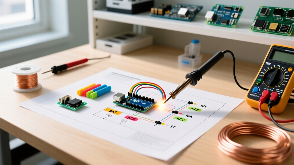
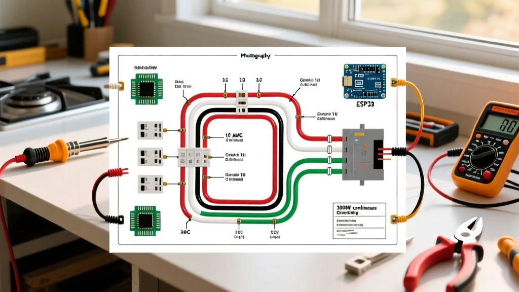
To ensure safety and optimal transmission performance, you must use a dedicated wiring diagram for a radio that integrates directly with a primary DC distribution panel or breaker block. This guide provides a comprehensive, panel-and-breaker-focused approach to wiring high-draw radios, ensuring your system meets the rigorous standards outlined by the ARRL Mobile Installation Guidelines and ABYC marine electrical codes.
The Core Wiring Diagram for a Radio (DC Panel Integration)
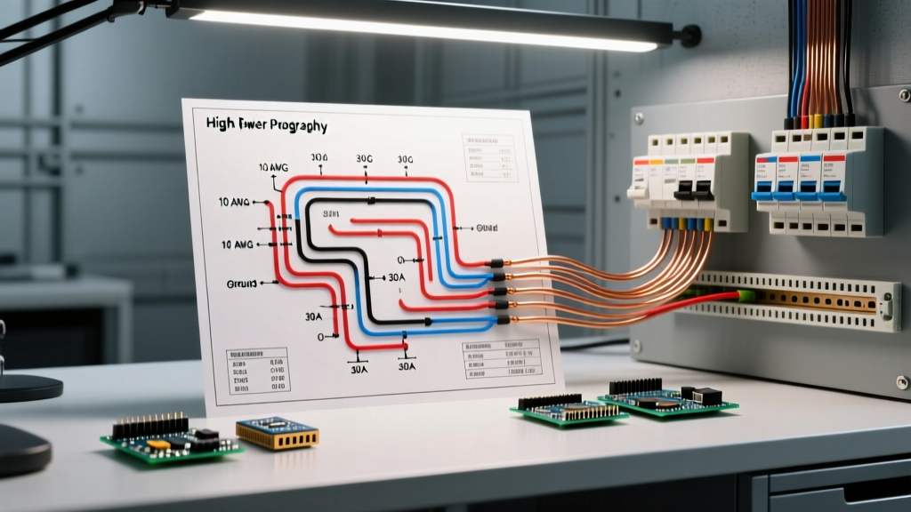
A proper high-current radio circuit bypasses the ignition switch and factory fuse boxes entirely. Below is the sequential circuit path you must follow when drafting your wiring diagram for a radio connected to a dedicated DC panel:
- Primary Power Source: 12V DC Battery Bank (Positive and Negative terminals).
- Main Overcurrent Protection: A Class T or ANL master fuse, or a high-amperage flush-mount breaker (e.g., 50A), installed within 7 inches of the positive battery terminal.
- DC Distribution Panel: A dedicated, bus-bar-style fuse block (e.g., Blue Sea Systems ST Blade) mounted securely to the chassis or bulkhead.
- Branch Circuit Protection: An appropriately sized ATC/ATO blade fuse housed inside the distribution panel, dedicated solely to the radio circuit.
- Branch Wiring: Marine-grade, tinned copper wire routed away from high-voltage AC lines and ignition sources.
- Inline RF Choke (Optional but Recommended):strong> A split-bead ferrite core placed near the radio chassis to prevent RF feedback.
- Radio Termination: Connection via Anderson Powerpole connectors or direct screw-terminal spade lugs, depending on the manufacturer's rear-panel design.
Expert Insight: Never rely solely on the inline fuse provided by the radio manufacturer. That fuse is designed to protect the radio's internal PCB from a short circuit; it is not rated to protect the branch wiring from melting if a chafing fault occurs between the panel and the transceiver. The panel-mounted branch fuse protects the wire.
Wire Gauge and Breaker Sizing Matrix
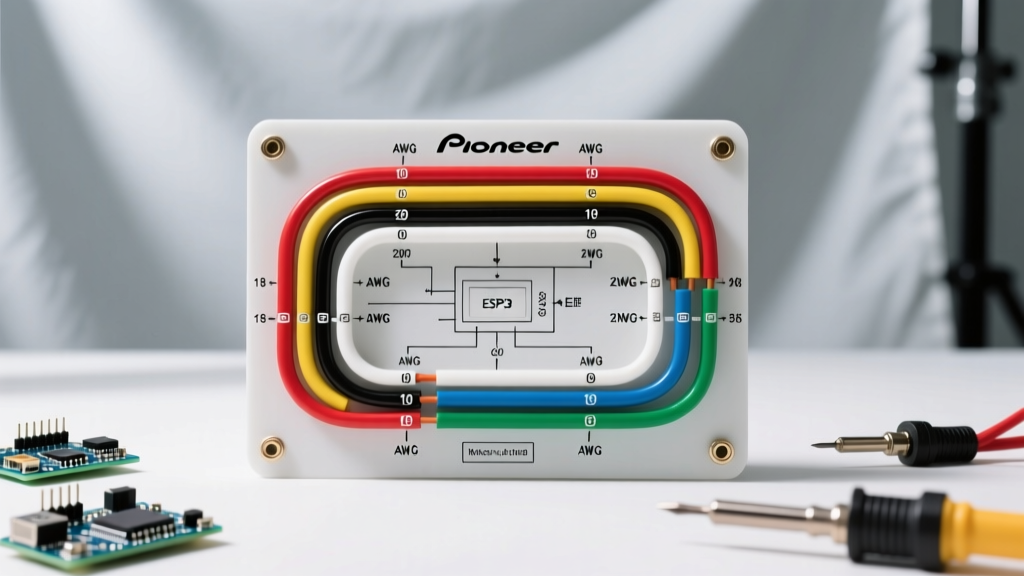
Selecting the correct wire gauge (AWG) and branch fuse size is dictated by the radio's maximum continuous current draw and the total length of the wire run (positive + negative). According to the Blue Sea Systems Circuit Protection 101 guidelines, the fuse must be sized to protect the wire, not the appliance. Therefore, the wire's ampacity must always exceed the fuse rating.
| Radio Model (Example) | Max TX Draw | Branch Fuse Size | Wire Gauge (Up to 10 ft) | Wire Gauge (10-15 ft) |
|---|---|---|---|---|
| Icom IC-7300 (HF) | 21.0A | 30A ATC | 10 AWG | 8 AWG |
| Yaesu FT-991A (HF/VHF) | 22.0A | 30A ATC | 10 AWG | 8 AWG |
| Kenwood TM-D710GA (Dual) | 12.5A | 15A ATC | 12 AWG | 10 AWG |
| Standard Horizon GX2200 | 6.0A | 10A ATC | 14 AWG | 12 AWG |
Note: Wire lengths represent the total round-trip distance from the DC panel to the radio and back to the panel's negative bus bar. Always round up wire length when calculating voltage drop.
Understanding the 3% Voltage Drop Rule
Communication radios are highly sensitive to voltage drop. If the voltage at the radio's rear terminals drops below 11.5V during a high-power transmission burst, the transceiver's internal protection circuitry will trigger an automatic shutdown or fold-back, drastically reducing your output power. For a 12V nominal system, a 3% drop equates to 0.36V. If your multimeter reads a 0.5V drop between the battery and the radio during transmit, your wire gauge is insufficient for the run length, or your panel bus bar connections are suffering from oxidation.
Selecting Your DC Distribution Panel and Breakers
In 2026, the market for DC distribution has standardized around modular, IP-rated fuse blocks. For mobile, marine, or base-station radio installations, we recommend the following components:
- Distribution Panel: The Blue Sea Systems 5025 ST Blade Fuse Block (6-circuit) is the industry standard. Priced around $28, it features independent negative bus bars for each circuit, which is critical for isolating radio ground returns from noisy accessory grounds.
- Branch Fuses: Use Bussmann ATC/ATO Silver-Plated Blade Fuses. Avoid cheap, bulk-bin aluminum fuses, as they introduce micro-resistance that compounds voltage drop over time. A pack of 50 Bussmann fuses costs approximately $18.
- Main Breaker: For the master feed from the battery to the DC panel, a Bussmann Series 184 Flush-Mount Circuit Breaker (50A or 80A) provides manual reset capabilities and acts as a primary kill switch for the radio bank. Expect to pay around $22 per unit.
Step-by-Step Panel Termination and Routing
Executing the wiring diagram for a radio requires meticulous termination. Poor crimps at the DC panel bus bar are the leading cause of intermittent radio reboots.
1. Stripping and Crimping
Strip the marine-grade tinned wire using a precision stripper to avoid nicking the copper strands. Use a closed-barrel, ratcheting crimper (such as the Knipex 48 18 160) for all ring and spade terminals. Ratcheting crimpers apply a uniform 4,000-PSI compression force, creating a gas-tight, cold-weld connection that resists vibration and thermal cycling.
2. Heat Shrink Application
Slide a piece of 3:1 adhesive-lined marine heat shrink over the wire before crimping. After crimping, apply heat until the adhesive bleeds out of the ends. This seals the copper against humidity and prevents galvanic corrosion at the panel terminal.
3. Torque Specifications
When securing the ring terminals to the Blue Sea ST Blade bus bars, do not overtighten. The brass screws on these panels are relatively soft. Tighten to a maximum of 18 in-lbs (2 Nm). Over-torquing will strip the threads or warp the bus bar, creating a high-resistance hotspot.
Edge Case Troubleshooting: RF Interference and Nuisance Tripping
A common issue when wiring high-power HF radios to a centralized DC panel is RF feedback. Because the DC panel acts as a central hub, RF energy can travel backward down the power leads, couple into adjacent circuits, and cause nuisance tripping of sensitive electronic breakers or disrupt nearby digital gauges.
The Solution: Install a common-mode choke on the radio's branch circuit. Pass both the positive and negative wires from the DC panel through a large toroidal ferrite core (such as the Fair-Rite 2643625002 or a Mix 31 equivalent) exactly three times before terminating at the radio. This creates a high-impedance barrier to RF frequencies while allowing DC current to pass with zero resistance. Additionally, ensure the DC panel's negative bus bar is bonded to the vehicle chassis or vessel's main ground bus using a heavy (4 AWG or larger) grounding strap, providing a low-impedity path for stray RF to dissipate safely.
Final Verification Checklist
Before applying power, verify the following against your wiring diagram:
- Main battery breaker is OFF.
- Branch fuse is removed from the DC panel.
- Multimeter continuity test between the positive radio lead and chassis ground reads 'OL' (Open Loop), confirming no short circuits.
- Insert branch fuse, turn on main breaker, and measure voltage at the radio's rear terminals. It should read within 0.1V of the battery's resting voltage.
For further reading on marine and mobile DC distribution standards, refer to the West Marine DC Wiring Advisor, which provides excellent visual references for bus bar routing and ABYC-compliant cable bundling techniques.