
Decoding the Harness: Modern Scooter Architecture
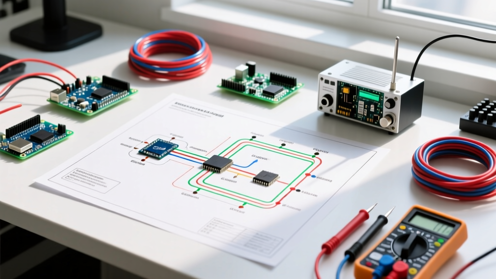
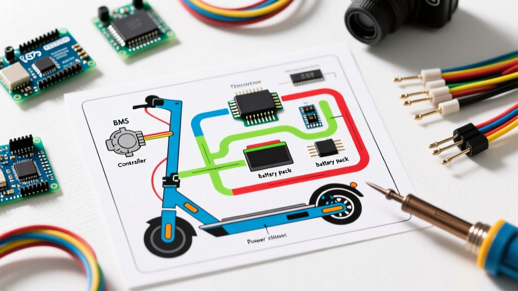
When a high-performance commuter scooter suddenly loses power or throws an error code, guessing which component failed is a costly mistake. A proper wiring diagram for electric scooter systems is not merely a map of connections; it is a sequential diagnostic flowchart. In 2026, the market has largely shifted from simple 36V brushed setups to complex 48V and 52V brushless architectures utilizing Field Oriented Control (FOC) controllers, such as the VESC 6.7 or proprietary Kelly Controllers. These systems integrate sophisticated Battery Management Systems (BMS), regenerative braking logic, and CAN bus communication lines.
To effectively troubleshoot, you must cross-reference physical multimeter readings with the schematic's logical nodes. This guide details how to trace faults through the primary subsystems: the throttle logic, motor hall sensors, and the BMS discharge paths.
Tracing the Throttle and Brake Logic Circuits
The most common point of failure on any scooter is the handlebar control cluster. When consulting your wiring diagram for electric scooter handlebars, you will typically see a 3-wire or 5-wire throttle connector and a 2-wire brake cut-off connector.
1. Diagnosing the 3-Wire Hall Effect Throttle
Unlike older potentiometer throttles, modern scooters use linear Hall effect sensors. Locate the throttle block on your schematic. You will see three lines: VCC (5V), GND, and SIGNAL.
- Verify the 5V Rail: Set your multimeter to DC Voltage. Backprobe the VCC and GND pins at the controller harness. If you read 0V, the fault is not the throttle; it is the controller's internal DC-DC buck converter. Replacing a $15 throttle won't fix a dead 5V logic rail.
- Test the Signal Sweep: Connect the black probe to GND and the red probe to the SIGNAL wire. At rest, the voltage should read between 0.8V and 1.1V. As you twist the throttle, it should smoothly sweep up to 3.1V - 4.2V (depending on the manufacturer). A jagged voltage sweep indicates internal magnet misalignment or water ingress.
2. Active Low vs. Active High Brake Cut-Offs
Schematics will label brake levers as either 'Active Low' (E-ABS) or 'Active High'.
- Active Low: The brake lever pulls the signal wire to ground (0V) to trigger the motor cut-off. If your scooter accelerates even when braking, check the schematic for a pull-up resistor on the controller board. If the resistor is burnt, the logic pin floats, ignoring the brake signal.
- Active High: The lever sends 5V or 12V to the controller. Use your diagram to trace this line to the optocoupler on the controller PCB. A blown optocoupler is a frequent edge case in scooters exposed to heavy rain.
Motor Phase Wires and Hall Sensor Mapping
Brushless DC (BLDC) hub motors rely on an 8-pin connector: three thick phase wires (Yellow, Green, Blue) and five thin Hall sensor wires. The wiring diagram for electric scooter motors will map these to the controller's MOSFET bridge.
Testing Phase Wire Integrity
If the scooter shudders, makes a grinding noise, or trips the controller's overcurrent protection, suspect phase wire failure.
- Disconnect the motor from the controller.
- Set the multimeter to the lowest Ohms setting (or continuity).
- Measure resistance between Yellow-Green, Green-Blue, and Blue-Yellow. You should see a very low, balanced resistance (typically 0.1 to 0.5 ohms).
- The Edge Case: If one pair reads infinite resistance (OL), the internal winding is severed. However, if all three read perfectly but the scooter still fails, consult the schematic to check the controller's phase shunt resistors. A blown 2-milliohm shunt will cause the controller to misread current draw, triggering a false 'Phase Short' error code.
Backprobing the 5-Pin Hall Connector
Hall sensors dictate rotor position. A single dead hall sensor will prevent the motor from starting, resulting in a 'jerking' sensation. According to Grin Technologies (Ebikes.ca), testing hall sensors dynamically requires backprobing the connector while the wheel is spun by hand.
With the 5V logic powered, probe the three signal wires (HA, HB, HC) against ground. As you rotate the wheel slowly, the voltage on each signal wire should toggle sharply between 0V and 5V. If a wire stays stuck at 5V or 0V, the internal Hall IC has failed, requiring a motor hub teardown and a $4 sensor replacement.
Multimeter Diagnostic Matrix
Use this reference table alongside your specific scooter schematic to isolate faults rapidly.
| Component | Diagram Trace Point | Expected Reading | Failure Symptom |
|---|---|---|---|
| DC-DC Buck Converter | VCC Logic Rail to GND | 4.9V - 5.1V DC | Dead dashboard, no throttle response |
| BMS Discharge MOSFETs | Pack Negative (B-) to P- | Near 0 Ohms (Closed) | Scooter turns on but cuts out under load |
| Motor Thermistor (NTC) | Temp Signal to GND | 10kΩ at 25°C | False 'Motor Overheat' error code |
| Charge Port (C-) | Charge Positive to C- | Pack Voltage (e.g., 54.6V) | Battery refuses to accept a charge |
BMS Fault Isolation: Charge vs. Discharge Ports
A critical distinction in any advanced wiring diagram for electric scooter battery packs is the separation of the Charge Negative (C-) and Pack/Discharge Negative (P-). The BMS uses two separate banks of MOSFETs to control current flow in and out of the lithium-ion cells.
Pro-Tip: If your scooter's dashboard lights up but the motor refuses to spin, do not immediately condemn the controller. Measure the voltage at the main battery connector. If it reads 0V under load but 54V at rest, your BMS discharge MOSFETs have tripped or blown due to a localized short or overcurrent event. As detailed in safety protocols by Battery University, a tripped BMS requires a specific 'wake-up' voltage applied to the charge port to reset the logic, or physical replacement of the MOSFET bank if the silicon has catastrophically failed.
The 'Ghost Drain' Edge Case
Some users report their scooter losing 10% battery over a week of sitting idle. Trace the schematic's 'Always On' lines. Many budget scooters wire the DC-DC converter directly to the main positive (B+), bypassing the main ignition key switch. This means the controller's microcontroller remains in a sleep state, drawing 15mA to 30mA continuously. The wiring fix involves relocating the DC-DC input wire to the switched side of the ignition lock cylinder, a modification that requires splicing 14 AWG silicone wire and adding an inline 5A automotive blade fuse.
Environmental Failures and Connector Corrosion
Even with perfect schematics, physical environment defeats electrical logic. The deck-to-stem connector (often a 6-pin or 9-pin waterproof Julet/Higo connector) is a notorious failure point. If your wiring diagram shows continuous paths for the headlight, brake light, and display, but the display flickers when turning the handlebars, the issue is micro-corrosion on the connector pins.
Do not simply spray contact cleaner and reassemble. Use a schematic to identify the high-current pins (usually the 12V headlight feed). If the pin shows black oxidation, the resistance has increased, causing a voltage drop that resets the dashboard logic. The only permanent repair is cutting off the stem harness and soldering a new IP67-rated connector, ensuring you use heat-shrink tubing with internal adhesive lining to prevent future moisture wicking.
Final Verification Steps
Always conclude your troubleshooting by verifying the CAN bus or UART communication lines if your scooter utilizes a smart dashboard (like the Ninebot or Apollo proprietary displays). According to research on EV communication protocols by the National Renewable Energy Laboratory (NREL), digital dashboards rely on clean square-wave data signals. If the TX/RX lines show physical continuity on your multimeter but the dashboard reads 'Error 14' (Communication Failure), the signal is likely degraded by electromagnetic interference (EMI) from unshielded phase wires. Rerouting the data cables away from the motor phase wires and wrapping them in copper foil shielding tape will often resolve ghost errors that no amount of component swapping can fix.